Clamp and machining equipment

A fixture and cylinder technology, applied in the field of fixtures and processing equipment, can solve the problems of insufficient machining accuracy of rod-shaped parts, and achieve the effect of solving insufficient machining accuracy

Inactive Publication Date: 2019-02-19
HUBEI TRI RING FORGING +1
View PDF12 Cites 1 Cited by
  • Summary
  • Abstract
  • Description
  • Claims
  • Application Information

AI Technical Summary

Problems solved by technology

[0004] In view of this, the application of the present invention provides a fixture and processing equipment to solve the problem of insufficient machining accuracy of rod-shaped parts in the prior art

Method used


Image

  • Clamp and machining equipment
  • Clamp and machining equipment
  • Clamp and machining equipment

Examples


no. 1 example

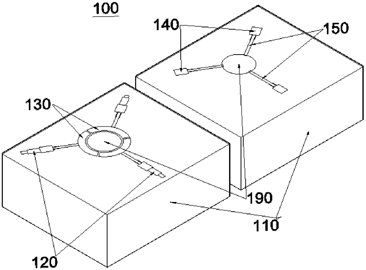
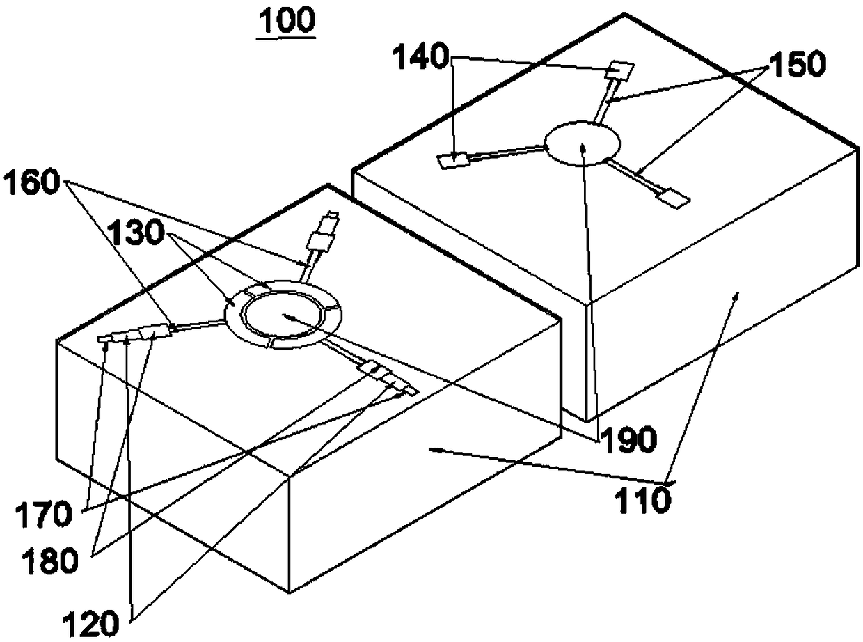
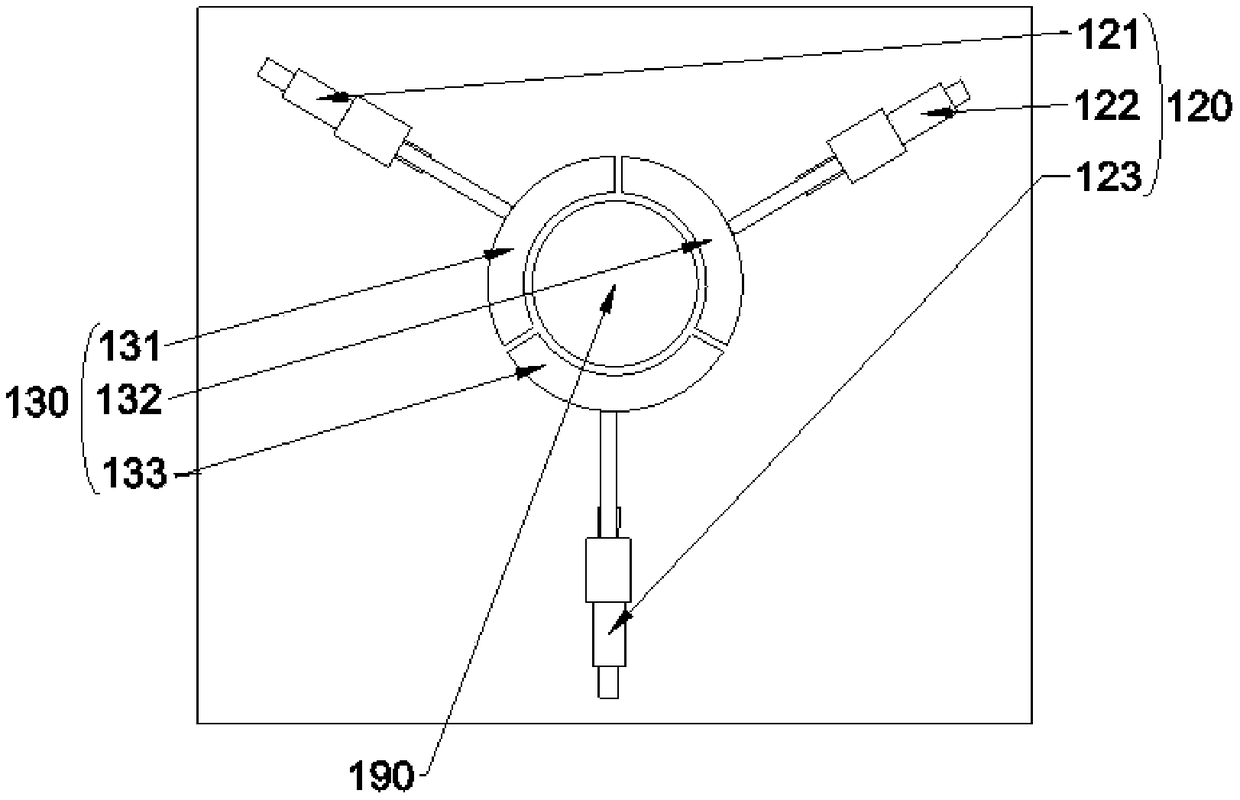
[0032] See figure 1 , figure 1 It shows the front and back first view structural schematic diagrams of the clamp provided by the embodiment of the present application. A clamp 100 provided by the application of the present invention, the clamp 100 includes: a housing 110, a plurality of fixed driving cylinders 120, a plurality of fixed blocks 130, a plurality of positioning driving cylinders 140 and a plurality of positioning rods 150; a plurality of fixed driving cylinders The number of 120 is the same as the number of a plurality of fixing holes, the number of a plurality of positioning drive cylinders 140 is the same as the number of a plurality of positioning rods 150; the housing 110 is provided with a fixing through hole 190, and the fixing through hole 190 runs through the housing 110. A fixed drive cylinder 120 is movably connected with a plurality of fixed blocks 130, a plurality of fixed blocks 130 are arranged around the fixed through hole 190 and a plurality of fi...

no. 2 example

[0051] See Figure 6 , Figure 6 A schematic structural diagram of the processing equipment provided by the embodiment of the present application is shown. The present application also provides a processing device 101 , the processing device 101 includes a processing device body, and the processing device body includes the above clamp 100 .

[0052] Wherein, it should be noted that the processing equipment 101 includes a processing equipment body, and the processing equipment body includes the clamp 100 as above.

[0053] The application of the present invention provides a fixture and processing equipment. A plurality of fixing blocks are arranged around the fixing through hole and the plurality of fixing blocks evenly surround the fixing through hole, and a plurality of positioning rods are arranged around the fixing through hole and the plurality of positioning rods are uniform Surround the fixed vias. In the case of a plurality of fixed blocks driven by the fixed driving...


PUM


Abstract

The invention provides a clamp and machining equipment. The problem that machining precision for rod-like parts in the prior art is not high is solved. The clamp comprises a shell, multiple fixing driving air cylinders, multiple fixing blocks, multiple positioning driving air cylinders and multiple positioning rods. The number of the multiple fixing driving air cylinders is the same as that of multiple fixing holes, the number of the multiple positioning driving air cylinders is the same as that of the multiple positioning rods, the shell is provided with a fixing through hole which penetratesthrough the shell, the multiple fixing driving air cylinders are movably connected with the multiple fixing blocks, the multiple fixing blocks are arranged on the periphery of the fixing through holeand evenly surround the fixing through hole, the multiple positioning driving air cylinders and the multiple positioning rods are movably connected, and the multiple positioning rods are arranged onthe periphery of the fixing through hole and evenly surround the fixing through hole.

Description

technical field [0001] The invention relates to the technical field of automobile processing, and relates to a fixture and processing equipment. Background technique [0002] The steering knuckle is one of the important parts in the steering axle of the car, which can make the car run stably and transmit the driving direction sensitively. Its function is to transmit and bear the front load of the car, support and drive the front wheel to rotate around the kingpin to make the car turn. In the driving state of the car, it bears variable impact loads. Therefore, the precision and hardness of the steering knuckle are important factors related to whether the car can drive safely. [0003] At present, in the process of processing the steering knuckle in the industry, the jig used to clamp the steering knuckle can still rotate after clamping, which leads to the deviation of the hole-drilling equipment when the steering knuckle is turned. And errors, so the machining accuracy of ...

Claims


Application Information

Patent Timeline
Patent Type & Authority Applications(China)
IPC IPC(8): B23Q3/08
CPCB23Q3/062B23Q3/08B23Q2703/04
Inventor 张运军张立宏吴华伟黄朝刘俊蔡以右梁文奎朱银丁华锋
Owner HUBEI TRI RING FORGING
Why Eureka
Try Eureka