
High-temperature directional solidification experimental device and experimental method for material under super-gravity environment

An experimental device, directional solidification technology, applied in the investigation phase/state change and other directions, which can solve problems such as directional solidification of difficult materials

Pending Publication Date: 2019-02-19
SHANGHAI INST OF CERAMIC CHEM & TECH CHINESE ACAD OF SCI
View PDF6 Cites 5 Cited by
  • Summary
  • Abstract
  • Description
  • Claims
  • Application Information

AI Technical Summary

Problems solved by technology

At present, the simple solidification of materials has been realized in the supergravity environment generated by the centrifuge, but it is difficult to realize the scientific experiment of controllable directional solidification of materials. However, as mentioned above, the directional solidification experiment itself is of great significance to the research of materials science.

Method used


Image

  • High-temperature directional solidification experimental device and experimental method for material under super-gravity environment
  • High-temperature directional solidification experimental device and experimental method for material under super-gravity environment

Examples


Embodiment Construction

[0053] The present invention will be further described below in conjunction with the following embodiments. It should be understood that the following embodiments are only used to illustrate the present invention, not to limit the present invention. The same or corresponding reference numerals in the respective drawings denote the same components, and repeated descriptions are omitted. At the same time, the following embodiments are only used to further explain the present invention and cannot be understood as limiting the scope of protection of the present invention. Some non-essential improvements and adjustments made by those skilled in the art based on the above content of the present invention belong to the protection of the present invention. range. The specific process parameters in the following examples are only an example in the appropriate range, that is, those skilled in the art can make selections within the appropriate range through the description herein, and are...


PUM

PropertyMeasurementUnit
compressive strengthaaaaaaaaaa
elastic modulusaaaaaaaaaa
thicknessaaaaaaaaaa

Abstract

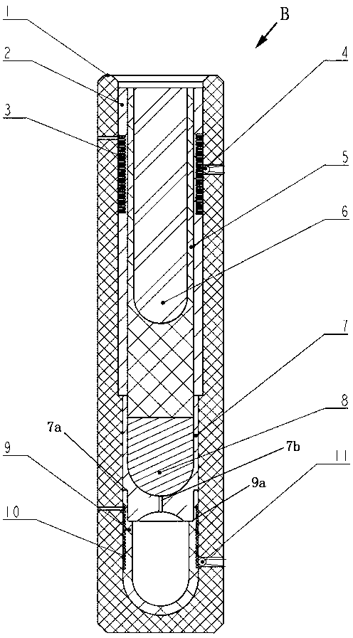
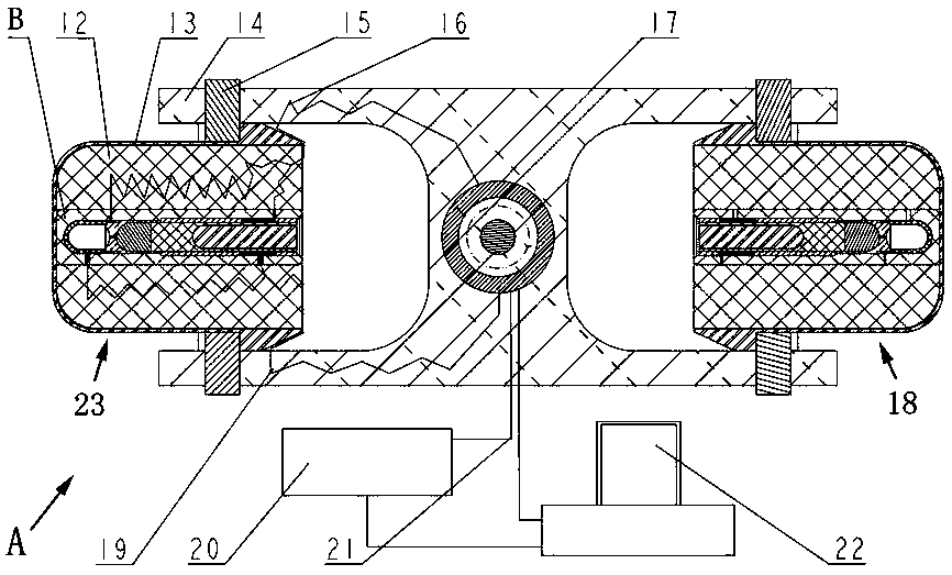
The invention provides a high-temperature directional solidification experimental device and an experimental method for a material under a super-gravity environment. The experimental device comprisesa centrifuge unit, an ampoule unit, a temperature control unit, and a control unit. The centrifuge unit comprises a first experimental unit and a second experimental unit. The ampoule unit is providedon the first experimental unit and comprises an ampoule sleeve, a secondary heating assembly, a meltable substrate cartridge, a meltable substrate, a crucible tube, and a primary heating assembly. The ampoule sleeve is provided with a hollow interior cavity. The secondary heating assembly is nested at the bottom of the inner side of the ampoule sleeve. The meltable substrate cartridge is mountedat the upper opening of the secondary heating assembly. The meltable substrate is placed in the hollow interior cavity of the meltable substrate cartridge. The crucible tube is nested inside the ampoule sleeve and the meltable substrate cartridge. The primary heating assembly is provided between the ampoule sleeve and the crucible tube. The meltable substrate flows into the hollow interior cavityof the secondary heating assembly after being melted. According to the high-temperature directional solidification experimental device and the experimental method for a material under a super-gravityenvironment, the directional solidification of the sample material under the condition of supergravity can be easily and conveniently realized without using a mechanical transmission mechanism such asa gear screw or an external device such as a motor.

Description

Technical field [0001] The invention relates to the technical field of high-temperature directional solidification of materials in a supergravity environment, in particular to an experimental device and an experimental method for high-temperature directional solidification of materials in a supergravity environment. Background technique [0002] Directional solidification is the use of forced means during the solidification process to establish a temperature gradient in a specific direction in the solidified metal-like unsolidified melt, so that the melt will nucleate on the gas wall and follow the direction opposite to the heat flow, as required The crystal orientation of the solidification technology. The biggest advantage of the directional solidification technology is that the alloy material prepared by it eliminates the influence between the matrix phase and the reinforcement phase interface, and effectively improves the overall performance of the alloy. At the same time, t...

Claims


Application Information

Patent Timeline
Patent Type & Authority Applications(China)
IPC IPC(8): G01N25/02
CPCG01N25/02
Inventor 盖立君艾飞汤美波潘秀红温海琴张明辉邓伟杰陈锟
Owner SHANGHAI INST OF CERAMIC CHEM & TECH CHINESE ACAD OF SCI
Learn More