Directional solidification method for metal material
A technology of directional solidification of metal materials, applied in the field of directional solidification of metal materials, can solve problems such as limited cooling effect and easy oxidation, achieve the effect of simplifying the production process, avoiding oxidation, and meeting the needs of research and application
- Summary
- Abstract
- Description
- Claims
- Application Information
AI Technical Summary
Problems solved by technology
Method used
Image
Examples
Embodiment 1
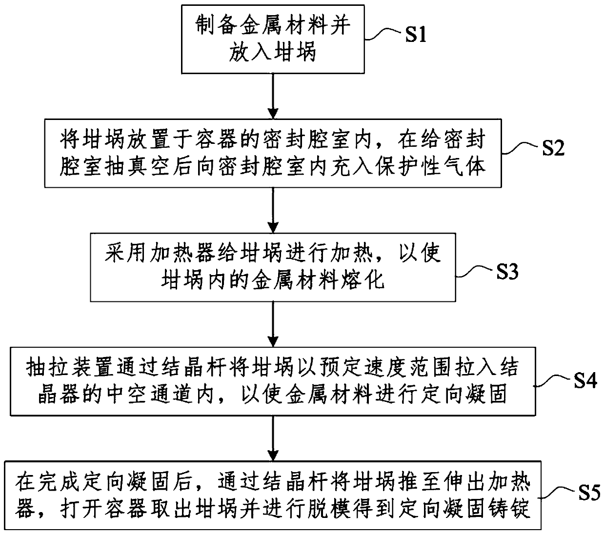
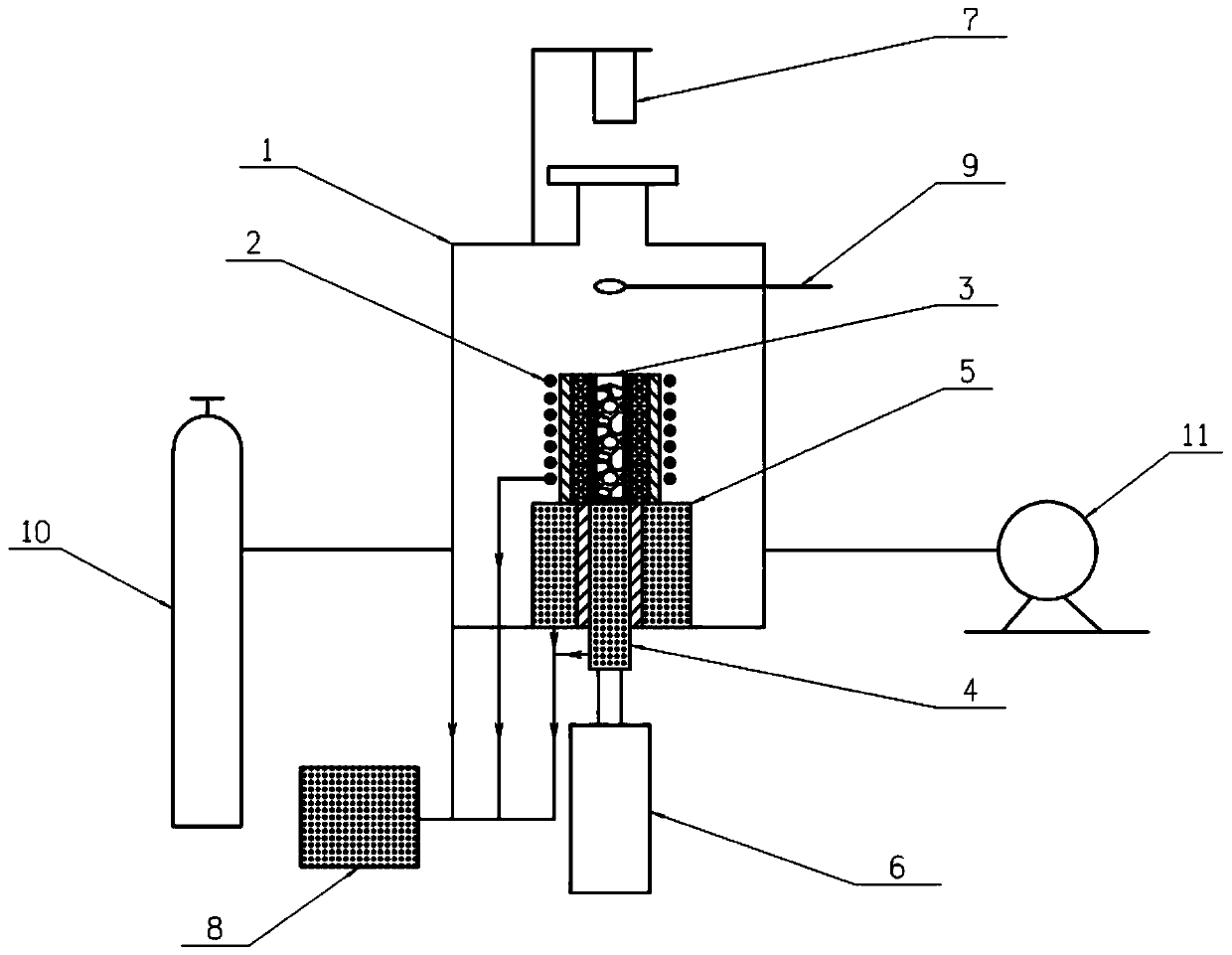
[0067] According to Fe 80 Cr 15 Ni 5 0.05kg-10kg of alloy raw material is prepared in atomic ratio, and put into the crucible 3, the height of the crucible 3 is 15mm-350mm, and the outer diameter is 15-120mm. Close the container 1, turn on the vacuum pump 11 to evacuate the sealed chamber to 1×10 -6 ~1×10 -4 Pa, then fill the sealed chamber with high-purity argon to 0.8×10 5 ~1×10 5 Pa, repeat this process 3 to 5 times. Turn on the high-frequency induction coil to adjust the current from 0 to 10A-35A, and heat the sample in the crucible 3 through the graphite heating jacket, wherein the graphite heating jacket has a thickness of 10mm-20mm and a height of 20mm-400mm. Through the infrared thermometer 7 set outside the glass observation window above the sealed chamber, the melting condition of the sample is judged, and the sample is kept warm for 5-30 minutes after melting, wherein the thickness of the insulation layer is 10mm-30mm. Turn on the power supply of the drawing ...
Embodiment 2
[0069] According to Fe 80 Cr 14.8 Ni 5 Ce 0.2 Prepare 8kg of alloy raw materials in atomic ratio, put Fe, Cr, Ni metal raw materials into crucible 3, the height of crucible 3 is 350mm, outer diameter is 100mm; Ce is put on the feeding spoon in feeding mechanism 9. Close the sealed chamber of high vacuum, turn on the vacuum pump 11 to pump the sealed chamber to 1×10 -6 Pa, then fill the sealed chamber with high-purity argon to 1×10 5 Pa, repeat this process 4 times. Turn on the high-frequency induction coil, adjust the current from 0 to 35A, and heat the sample in the crucible 3 through the graphite heating jacket, wherein the graphite heating jacket has a thickness of 20mm and a height of 400mm. Through the infrared thermometer 7 arranged outside the glass observation window above the sealed chamber, the melting condition of the sample is judged. After the sample is melted, it is kept warm for 20 minutes, wherein the thickness of the insulation layer is 30mm. Rotate the ...
Embodiment 3
[0071] According to Ti 80 Ni 10 al 5 Cr 5 0.1 kg of alloy raw material was prepared in atomic ratio, and put into crucible 3, the height of crucible 3 was 20 mm, and the outer diameter was 15 mm. Close the sealed chamber of high vacuum, turn on the vacuum pump 11 to pump the sealed chamber to 1×10 -4 Pa, then fill the sealed chamber with high-purity argon to 0.8×10 5 Pa, repeat this process 3 times. Turn on the high-frequency induction coil, adjust the current from 0 to 10A, and heat the sample in the crucible 3 through the graphite heating jacket, wherein the graphite heating jacket has a thickness of 10mm and a height of 25mm. Through the infrared thermometer 7 arranged outside the glass observation window above the sealed chamber, the melting condition of the sample is judged, and the sample is kept warm for 5 minutes after melting, wherein the thickness of the insulation layer is 15mm. Turn on the power supply of the drawing device 6, set the motor speed to 1r / min, t...
PUM
| Property | Measurement | Unit |
|---|---|---|
| melting point | aaaaa | aaaaa |
| height | aaaaa | aaaaa |
| thickness | aaaaa | aaaaa |
Abstract
Description
Claims
Application Information
 - R&D
- Intellectual Property
- Life Sciences
- Materials
- Tech Scout
- Unparalleled Data Quality
- Higher Quality Content
- 60% Fewer Hallucinations
Browse by: Latest US Patents, China's latest patents, Technical Efficacy Thesaurus, Application Domain, Technology Topic, Popular Technical Reports.
© 2025 PatSnap. All rights reserved.Legal|Privacy policy|Modern Slavery Act Transparency Statement|Sitemap|About US| Contact US: help@patsnap.com


