
A sensory control display panel and a sensory control display device

A technology for display panels and display devices, which can be used in instruments, semiconductor devices, computing, etc., and can solve problems such as occupying space

Active Publication Date: 2022-04-26
BOE TECH GRP CO LTD +1
View PDF0 Cites 0 Cited by
  • Summary
  • Abstract
  • Description
  • Claims
  • Application Information

AI Technical Summary

Problems solved by technology

[0005] The present invention provides a sensory control display panel and a sensory control display device to solve the problem that in the existing display device, the distance sensor that uses near-infrared emission and near-infrared reception for distance detection needs to occupy a certain space and can only realize the distance Detect problems with this single function

Method used


Image

  • A sensory control display panel and a sensory control display device
  • A sensory control display panel and a sensory control display device
  • A sensory control display panel and a sensory control display device

Examples


Embodiment 1

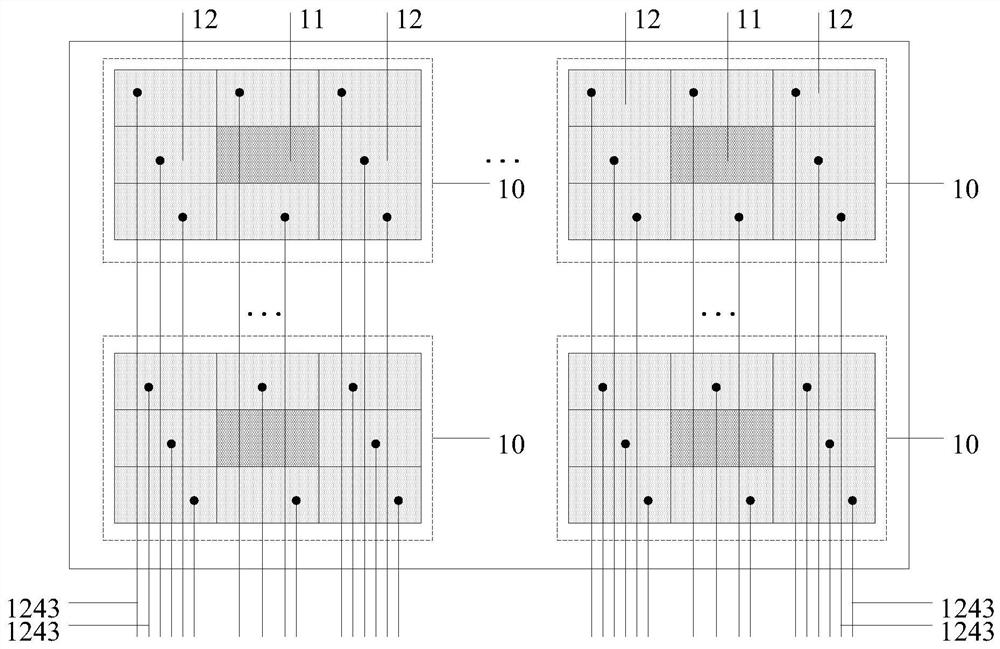
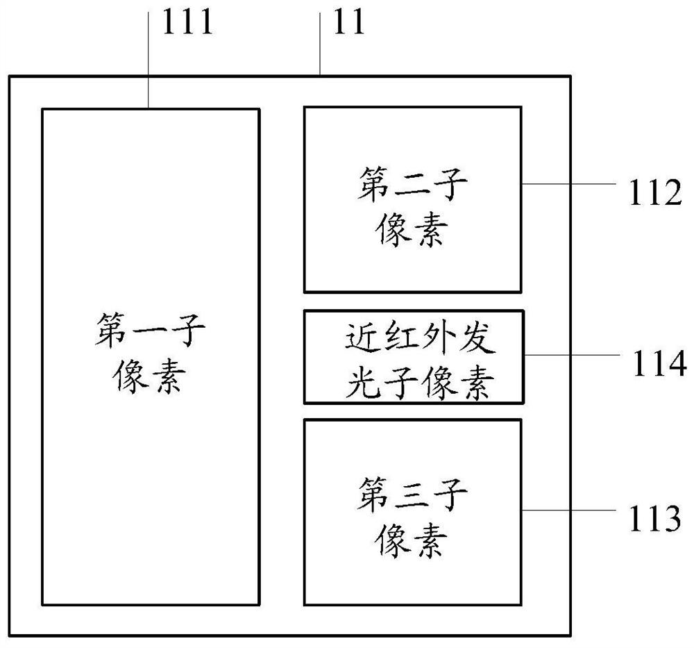
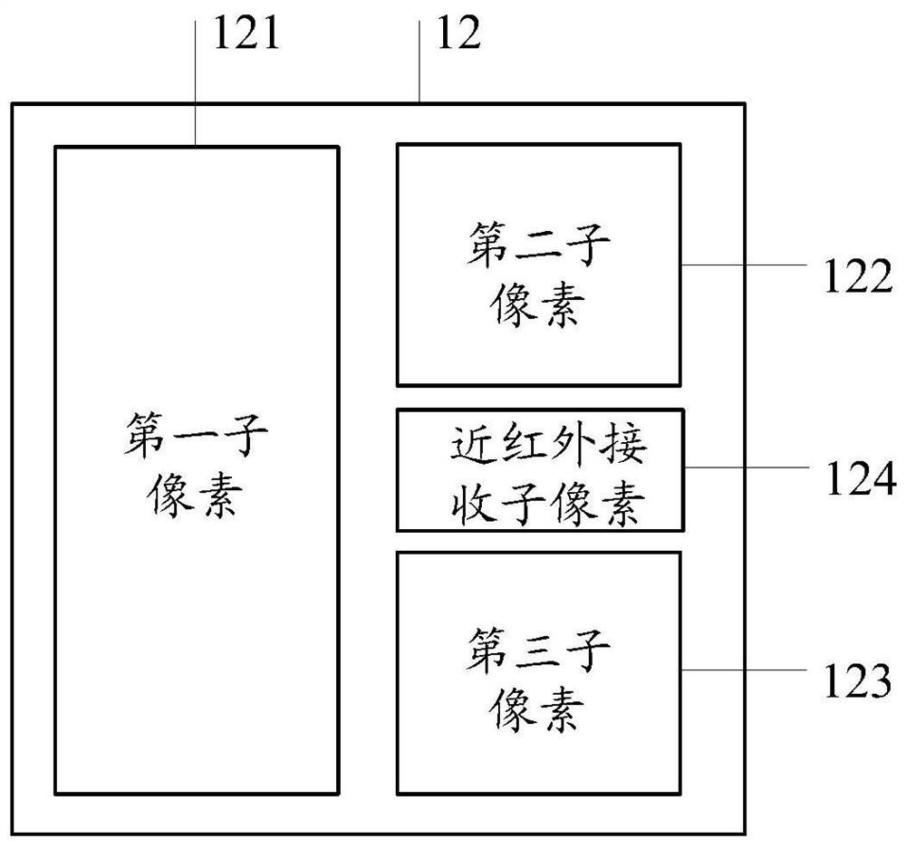
[0070] refer to figure 1 , showing a schematic structural diagram of a sensory control display panel according to an embodiment of the present invention, figure 2 shows a schematic structural diagram of a first pixel in an embodiment of the present invention, image 3 A schematic structural diagram of a second pixel according to an embodiment of the present invention is shown.

[0071] An embodiment of the present invention provides a sensor-controlled display panel, including a plurality of pixel areas 10 located in the display area, each pixel area 10 includes a first pixel 11 and a second pixel 12, and the first pixel 11 includes at least one display light-emitting element Pixel and near-infrared emitting sub-pixel 114 , the second pixel 12 includes at least one display emitting sub-pixel and near-infrared receiving sub-pixel 124 .

[0072] The near-infrared emitting sub-pixel 114 is configured to emit near-infrared light; the near-infrared receiving sub-pixel 124 is con...

Embodiment 2

[0137] An embodiment of the present invention provides a sensor-controlled display device, including the above-mentioned sensor-controlled display panel.

[0138] refer to Figure 25 , shows a schematic structural diagram of a sensory control display device according to an embodiment of the present invention.

[0139] Wherein, the sensory control display device further includes a sensory control identification module 21; the sensory control identification module 21 is connected to the sensory control signal line 1243 of the near-infrared receiving sub-pixel, and is configured to determine the external the position of the object.

[0140] by Figure 25 Take the pixel arrangement shown as an example to illustrate the principle of the present invention to detect the position and movement track of an external object:

[0141] Each pixel area 10 includes one first pixel 11 and eight second pixels 12. To simplify the structural diagram, only the near-infrared light-emitting sub-p...


PUM


Abstract

The invention provides a sensory control display panel and a sensory control display device, which relate to the field of display technology. The present invention arranges a plurality of pixel areas in the display area, each pixel area includes a first pixel and a second pixel, the first pixel includes a near-infrared emitting sub-pixel, the second pixel includes a near-infrared receiving sub-pixel, and the near-infrared emitting sub-pixel The pixels emit near-infrared light, and when an external object approaches the sensory control display panel, the near-infrared receiving sub-pixel receives the near-infrared light reflected back by the external object to detect the position of the external object. By integrating a near-infrared emitter into a first pixel as a near-infrared emitting sub-pixel, and integrating a near-infrared receiver into a second pixel as a near-infrared receiving sub-pixel, based on a near-infrared emitting sub-pixel and a near-infrared receiving sub-pixel, It can detect the position and movement trajectory of external objects, so as to realize sensory control interaction functions such as gesture sensing and eye control without taking up extra space.

Description

technical field [0001] The present invention relates to the field of display technology, in particular to a sensory control display panel and a sensory control display device. Background technique [0002] With the continuous development of display technology, more and more additional functions are integrated into the display device. From the initial push-button mobile phone to today's smart touch mobile phone, the way of human-computer interaction has undergone earth-shaking changes. The interactive method is likely to become the next generation of human-computer interaction. [0003] Existing sensory control interaction methods mainly include voice control, light sensing, etc., while sensory control interaction methods that use near-infrared emission and near-infrared reception are mainly used in distance sensors. [0004] However, in the display device, the distance sensor, which uses near-infrared emission and near-infrared reception for distance detection, needs to occ...

Claims


Application Information

Patent Timeline
Patent Type & Authority Patents(China)
IPC IPC(8): H01L27/32G06F3/042
CPCG06F3/0421H10K59/40G06F3/0412
Inventor 孙世成胡双霍培荣田建飞王志强
Owner BOE TECH GRP CO LTD
Learn More