
Multi-functional cable bracket

A cable tray, multi-functional technology, applied in electrical components and other directions, can solve problems such as increased risk, low work efficiency, cable entanglement, etc., to achieve the effect of improving stability, ensuring bearing capacity, and enhancing stability

Pending Publication Date: 2019-02-19
CHONGQING HAIZHUANG WINDPOWER ENG CO LTD
View PDF0 Cites 0 Cited by
  • Summary
  • Abstract
  • Description
  • Claims
  • Application Information

AI Technical Summary

Problems solved by technology

However, in the working environment of modern marine engineering, due to the special environment of the ocean, the cables are particularly prone to contact with water. The current cable bracket is just a simple bracket, which does not have a good ventilation effect, which is not conducive to The drying of the cables increases the risk
Moreover, in the current cable installation process, it is often necessary to install and operate multiple cables at the same time. In a high-altitude environment, the cables are stacked on the existing cable brackets, which is easy to cause the cables to be entangled, which is beneficial to the pick-and-place of the cables. Moreover, the cables are placed on the cable brackets, and the cables are often fixed by cable ties, which is troublesome and cannot be taken and placed at any time, so the work efficiency is low, which is not conducive to the installation of the cables.

Method used


Image

  • Multi-functional cable bracket
  • Multi-functional cable bracket
  • Multi-functional cable bracket

Examples


Embodiment 1

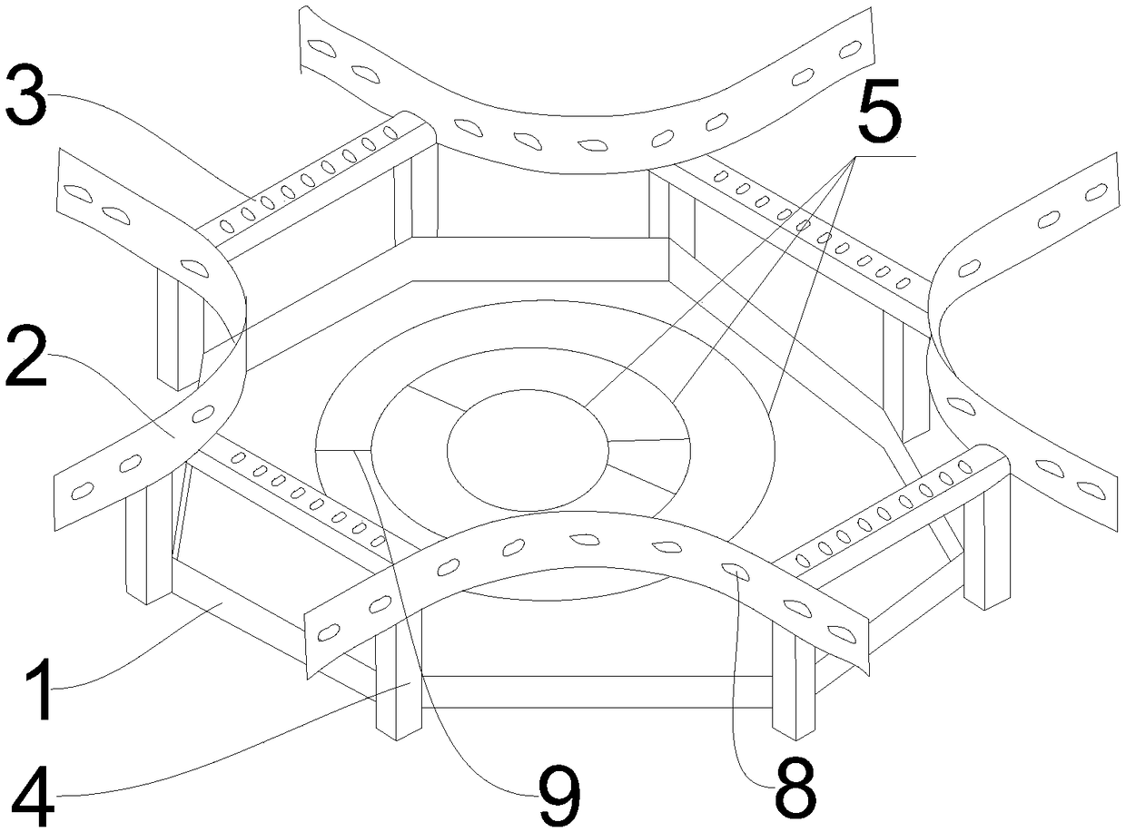
[0031] Such as figure 1 with figure 2 As shown, a multi-functional cable tray includes four symmetrically arranged right-angled arc-shaped side plates 2 with the centers facing outwards. The line connecting the centers of the right-angled arc-shaped side plates 2 forms a square, and two adjacent Two right-angle arc side panels 2 are connected by horizontal beams 3;

[0032] The side wall of the crossbeam 3 is connected to the top end of the vertically erected connecting column 4, and the bottom end of the connecting column 4 is provided with a cable storage device for classifying and storing the cables.

[0033] Specifically, both the beam 3 and the right-angle arc side plate 2 are provided with a first through hole 8 for cables to pass through.

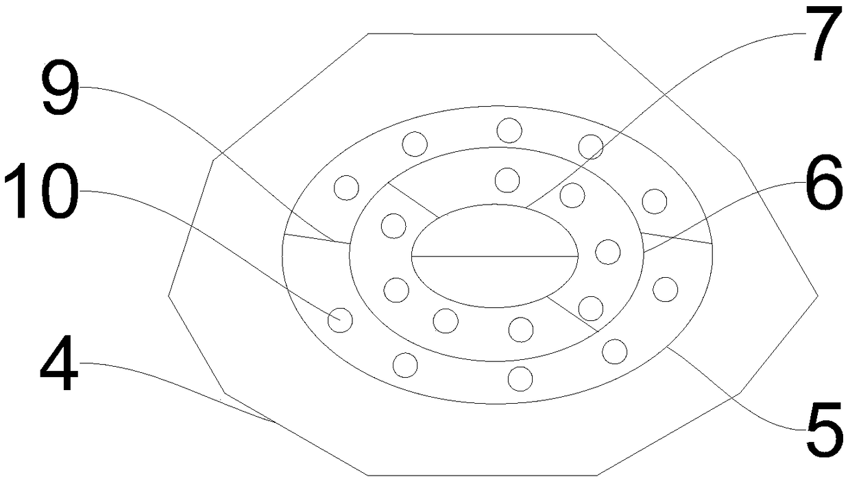
[0034] Specifically, the cable storage device includes a tray 1, the side wall on the tray 1 is fixedly connected to the bottom end of the connecting column 4, and several annular partition plates 5 are arranged inside the tray 1,...

Embodiment 2

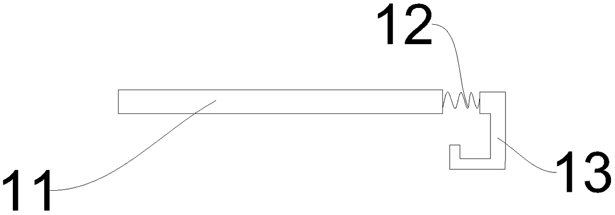
[0037] Such as figure 2 with image 3 As shown, the difference from Embodiment 1 is that a cable fixing device for fixing cables is provided between any two adjacent partition plates 5 . There are two cable fixing devices between any two adjacent partition plates 5, and the cable fixing devices are arranged symmetrically.

[0038] Specifically, the cable fixing device includes a fixing column 11, a spring 12 and a hook 13, one end of the fixing column 11 is connected to one end of the spring 12, and the end of the spring 12 away from the fixing column 11 is connected to the One end of the hook 13 is connected, and one end of the fixed column 11 away from the spring 12 is hinged to the side wall of a partition plate 5, and the end of the hook 13 away from the spring 12 is connected to the adjacent another partition plate The through hole on the sidewall of 5 is flexibly connected.

[0039] The specific implementation method is that after the cable is stored between two adja...

Embodiment 3

[0041] The difference from Embodiment 1 is that the tray 1 is provided with several second through holes 10 for heat dissipation and ventilation.


PUM


Abstract

The invention relates to the field of cable brackets and in particular to a multi-functional cable bracket. The multi-functional cable bracket comprises a plurality of symmetrically installed right-angle arc-shaped side plates. Connecting lines of circle centers of a plurality of the right-angle arc-shaped side plates are positioned in a same horizontal plane. Two neighboring right-angle arc-shaped side plates are connected through a horizontally installed cross beam. The side wall of the cross beam is connected with the top end of a vertically installed connecting column. The bottom end of the connecting column is provided with a cable storage device which is used for classifying and storing a cable. An opening-type structure of the multi-functional cable bracket is stable in structure, and beneficial to dry and ventilate the cable. The cable can be split by a separating plate. A cable fixing device on the separating plate is capable of avoiding using a cable binding belt, simply andconveniently taking and placing the cable on the separating plate, and improving installing efficiency and using efficiency of the cable.

Description

technical field [0001] The invention relates to the field of cable brackets, in particular to a multifunctional cable bracket. Background technique [0002] Cable Tray The first bracket to support and place cables. Cable trays are widely used in the power supply field for carrying cables. However, in the working environment of modern marine engineering, due to the special environment of the ocean, the cables are particularly prone to contact with water. The current cable bracket is just a simple bracket, which does not have a good ventilation effect, which is not conducive to The drying of the cable increases the risk. Moreover, in the current cable installation process, it is often necessary to install and operate multiple cables at the same time. In a high-altitude environment, the cables are stacked on the existing cable brackets, which is easy to cause the cables to be entangled, which is beneficial to the pick and place of the cables. And the cable is placed on the c...

Claims


Application Information

Patent Timeline
Patent Type & Authority Applications(China)
IPC IPC(8): H02G3/04H02G3/03
CPCH02G3/03H02G3/0456
Inventor 蒲洪年张明宇秦海明王冬春黄孟阳杨玺
Owner CHONGQING HAIZHUANG WINDPOWER ENG CO LTD
Learn More