
Test tube capping device

A technology for test tubes and test tube racks, which is applied in the field of test tube capping devices, can solve problems such as low work efficiency, high use cost, and endangering the health of operators, and achieve the effects of reducing labor intensity, improving work efficiency, and convenient operation

Pending Publication Date: 2019-02-22
郑州金域临床检验中心有限公司
View PDF0 Cites 2 Cited by
  • Summary
  • Abstract
  • Description
  • Claims
  • Application Information

AI Technical Summary

Problems solved by technology

Therefore, the manual capping method needs to be capped one by one, which is time-consuming and laborious, resulting in low work efficiency; in addition, due to improper force, the test tube may be broken and the operator may be damaged, and the operator may be exposed to the environment due to the volatilization of the sample in the test tube. In a highly pathogenic environment, the health of the operator is at risk
[0004] In addition, there is an electric capping machine in the prior art, which uses an automatic device to replace manual work, but the capping method is usually performed individually. Although it can reduce labor intensity, the cost of use is high, and it is not suitable for small and medium-sized laboratories.

Method used


Image

  • Test tube capping device
  • Test tube capping device

Examples


Embodiment Construction

[0025] The following will clearly and completely describe the technical solutions in the embodiments of the present invention with reference to the accompanying drawings in the embodiments of the present invention. Obviously, the described embodiments are only some, not all, embodiments of the present invention. Based on the embodiments of the present invention, all other embodiments obtained by persons of ordinary skill in the art without making creative efforts belong to the protection scope of the present invention.

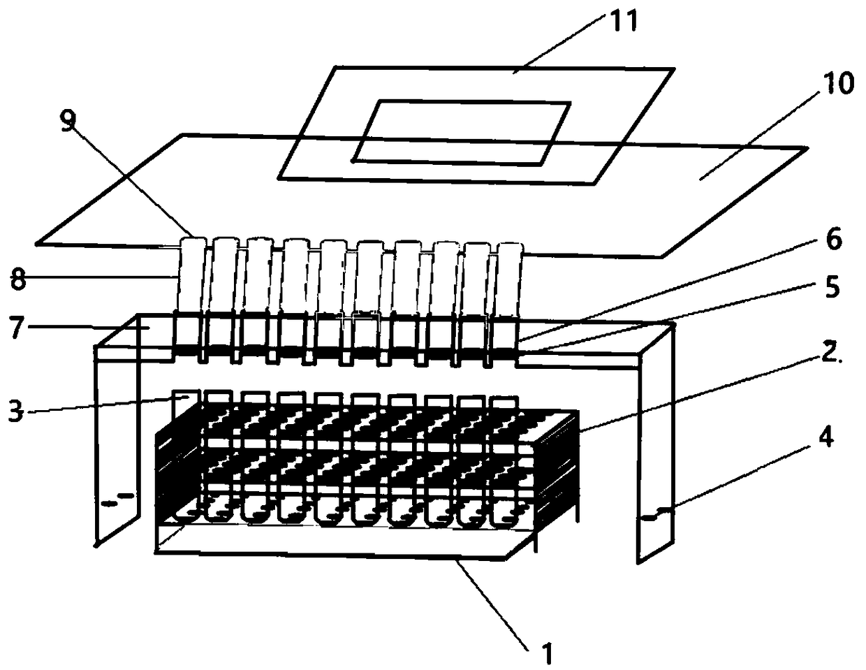
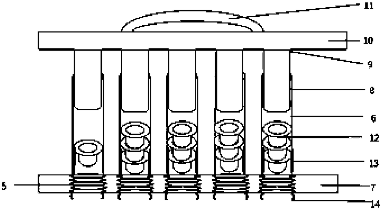
[0026] Please refer to figure 1 with figure 2 , figure 1 A schematic diagram of a three-dimensional structure of a test tube capping device provided by a specific embodiment of the present invention; figure 2 It is a schematic diagram of a front view partial structure of a test tube capping device provided by a specific embodiment of the present invention.

[0027] A test tube capping device provided by the embodiment of the present invention includes: a ...


PUM


Abstract

The invention discloses a test tube capping device. The test tube capping device comprises a fixing plate, a pressing plate and a test tube rack, wherein a plurality of cap accommodating cylinders forplacing caps are arranged on the fixing plate, cap falling holes in one-to-one correspondence to the cap accommodating cylinders are formed in the fixing plate, the fixing plate is located at the upper part of the pressing plate, and a plurality of pressing rods in one-to-one correspondence to the cap accommodating cylinders are arranged at the bottom of the pressing plate, and are glidingly connected in the cap accommodating cylinders for pushing the caps to move downwards; the test tube rack is located at the bottom of the pressing plate, and a plurality of test tubes in one-to-one correspondence to the cap accommodating cylinders are arranged on the test tube rack; the caps in the cap accommodating cylinders are pressed at openings of the test tubes by the pressing rods when the pressing plate moves downwards. During use, the test tube rack needs to be placed at the bottom of the fixing plate, so that the openings of the test tubes are right aligned with the cap falling holes, thendownward force is applied to the pressing plate, and the caps can be extruded at the openings of the test tubes by the pressing rods. Accordingly, a plurality of the test tubes can be capped simultaneously, labor intensity can be effectively reduced, working efficiency is improved, and the device is simple in structure, convenient to operate and lower in cost.

Description

technical field [0001] The invention relates to the technical field of test tubes, in particular to a test tube capping device. Background technique [0002] The test tube is a container for storing the substance to be tested. The function of the test tube cover is to seal the test tube to prevent the contents of the test tube from being contaminated or volatilized, which will affect the quality of the subsequent use of the specimen. [0003] The existing test tube capping method is usually carried out manually, that is, the operator holds the test tube and the test tube cover respectively with both hands, then presses the test tube cover into the test tube with the thumb, and finally puts the test tube into the test tube rack. Therefore, the manual capping method needs to be capped one by one, which is time-consuming and laborious, resulting in low work efficiency; in addition, due to improper force, the test tube may be broken and the operator may be damaged, and the opera...

Claims


Application Information

Patent Timeline
Patent Type & Authority Applications(China)
IPC IPC(8): B01L3/14
CPCB01L3/50825Y02W90/10
Inventor 李利娟尚牧牧魏天佑潘素梅秦建平
Owner 郑州金域临床检验中心有限公司
Features
  • Generate Ideas
  • Intellectual Property
  • Life Sciences
  • Materials
  • Tech Scout
  • Unparalleled Data Quality
  • Higher Quality Content
  • 60% Fewer Hallucinations
Learn More