Tube push bench rack electric control protection circuit and protection method thereof

A protection circuit and electrical control technology, applied in rolling mill control devices, manufacturing tools, metal rolling, etc., can solve major accidents, fast pushing speed and other problems, and achieve the effect of solving unexpected shutdowns and avoiding flying car accidents

Pending Publication Date: 2019-02-22
DAYE SPECIAL STEEL CO LTD
View PDF0 Cites 2 Cited by
  • Summary
  • Abstract
  • Description
  • Claims
  • Application Information

AI Technical Summary

Problems solved by technology

[0004] Because of the fast pushing speed, if there is a sudden power failure or other fault shutdown during the rolling process, if no effective measures a

Method used


Image

  • Tube push bench rack electric control protection circuit and protection method thereof

Examples


Embodiment 1

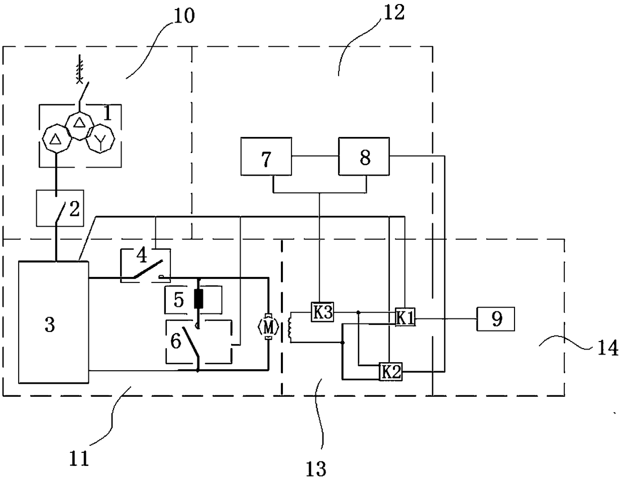
[0073] When the device is in normal operation, various closed-loop adjustments and controls of speed and current are performed by Siemens 6RA70 speed control device. When the speed regulating device fails, it must turn off all thyristor components for armature regulation. Therefore, a bypass switch is designed in the armature circuit. The bypass switch 6 is connected in series with the braking resistor and then connected in parallel with the motor. Turning on the bypass switch can quickly consume the energy of the motor to the braking resistor, thereby achieving the purpose of braking and stopping. The specific method is as follows:

[0074] When the DC speed control device 3 fails, it immediately blocks the thyristor assembly for armature regulation, and at the same time sends the status word to the PLC. The circuit of the electromechanical armature M and the braking resistor 5 realizes the energy consumption braking of the electromechanical armature M.

[0075] A total of ...

Embodiment 2

[0077] The specific method of rapid recovery after the motor loses magnetism is as follows:

[0078] When the excitation detection circuit detects that the excitation power supply K1 is de-excitation, the excitation detection device K3 sends a de-excitation signal to the PLC, and the PLC control system 7 immediately closes the contactor of the backup excitation power supply K2, puts in the backup excitation power supply, and then restores the motor excitation system. The motor excitation system continues to run, the DC motor forms a reliable magnetic field, and the direction and size of the armature circuit current is controlled by the DC speed regulating device 3, finally realizing the brake stop of the motor.

[0079] Using this method to test the above-mentioned situation 80 times in total, all can ensure the normality of the input and output signals, and realize the brake stop of the motor.

Embodiment 3

[0081] The PLC device independently controlled by the transmission cabinet, and the disposal when abnormality occurs. The specific method is as follows:

[0082] The two independent PLC systems have normal interlocking signals from the detection devices. When the normally used PLC control system 7 is abnormally shut down, the standby PLC system 8 will immediately start the emergency control program after detecting the signal, and the DC speed control device 3 will implement the reverse operation. Connect the brake to brake the motor to stop, and give an alarm signal of "PLC system abnormality".

[0083] Using this method to test the above situation 70 times, all can ensure the normality of the interlocking signal, the emergency program can be put into use normally, and the purpose of priority for motor braking and shutdown has been achieved.


PUM


Abstract

The invention discloses a tube push bench rack electric control protection circuit and a protection method thereof. The protection circuit comprises a power consumption braking circuit, an excitationpower supply redundancy circuit, a PLC system redundancy circuit and a UPS circuit. The invention discloses the protection circuit used after abnormal power failures of a tube push bench rack and theelectric control parking protection method; and according to the method, a new electrical control idea is adopted to prevent the tube push bench rack from running out of control after a sudden power failure happens in the movement process, and corresponding programs are designed in a targeted manner according to various possibilities of various component damage and power failures through perfect backup power supply and element redundancy design. The technology can effectively solve unplanned shutdown caused by any reason, the rack can be subjected to controlled stopping stably and reliably, and the purpose of run-away accidents is achieved.

Description

technical field [0001] The invention belongs to the technical field of electrical control, and in particular relates to an electrical control protection circuit for a pipe jacking machine rack and a protection method thereof. Background technique [0002] The pipe jacking machine is an important key equipment in the hot rolling process of seamless steel pipes. Its technological characteristics are: the perforated capillary tube is locked with the head of the mandrel through the necking machine, and then fed into the pipe jacking machine, and the rack pushes the core Rod, the capillary and mandrel pass through more than a dozen three-roller dies on the pipe jacking machine body, and the metal is extruded and deformed into a thin-walled pipe with a suitable wall thickness. [0003] The transmission structure of the pipe jacking machine is as follows: two 2250KW DC motors connect two gears through the reducer, and the gears mesh with the large rack, so that the rack is dragged ...

Claims


Application Information

Patent Timeline
IPC IPC(8): B21B19/04B21B37/78
CPCB21B19/04B21B37/78
Inventor 朱文峰王成郑文波
Owner DAYE SPECIAL STEEL CO LTD
Why Eureka
Try Eureka