Al technical title is built by PatSnap Al team. It summarizes the technical point description of the patent document.
A belt conveyor and braking system technology, applied in the direction of conveyors, transportation and packaging, etc., can solve the problems of automatic control of braking time, belt conveyor out of control, speeding accidents, etc., to avoid speeding accidents and Operator casualties, compact structure, and the effect of avoiding gas explosion
Inactive Publication Date: 2015-04-08
CHINA UNIV OF MINING & TECH
View PDF7 Cites 0 Cited by
Summary
Abstract
Description
Claims
Application Information
AI Technical Summary
This helps you quickly interpret patents by identifying the three key elements:
Problems solved by technology
Method used
Benefits of technology
Problems solved by technology
[0003] There will be two problems in the working process of the down-conveyor belt conveyor: one is that overspeed will occur during the transportation process, and the speed will become faster and faster, and eventually the belt conveyor will lose control, resulting in a speeding accident; the other is that during the working process If the braking system cannot respond quickly during a sudden power failure, the material on the conveyor belt will drive the conveyor belt down, and the speed will become faster and faster, which will also lead to a speeding accident
Although the hydraulic viscous brake overcomes the disadvantage that the temperature of the disc brake cannot be controlled, it requires electrical control, and its braking time cannot be automatically controlled in the case of a sudden power failure
Method used
Image
Click on the blue label to locate the original text in one second.
Reading with bidirectional positioning of images and text.
Examples
Embodiment Construction
[0012] The present invention will be further described below in conjunction with accompanying drawing.
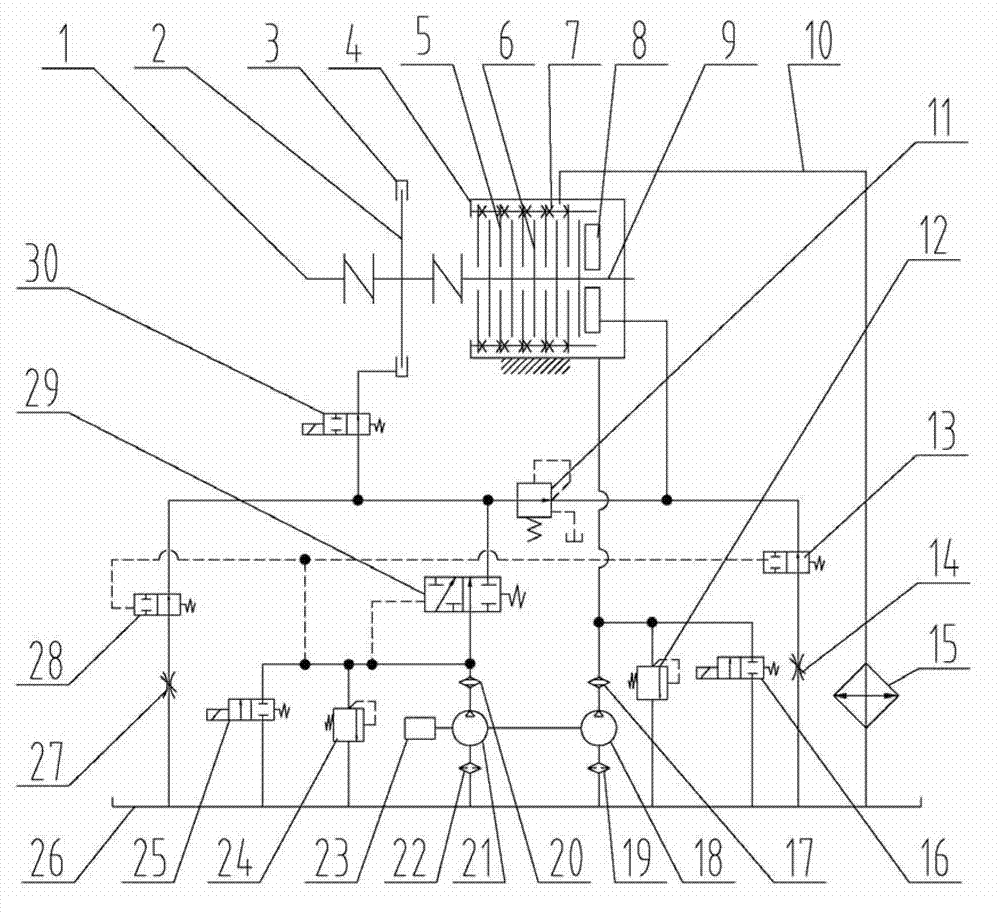
[0013] like figure 1 As shown, a brake system for down-conveyor belt conveyor, including belt conveyor drive roller shaft 1, hydraulic brake 4, propulsion cylinder 8, hydraulic brake shaft 9, throttle valve I14, lubricating oil pump 18. Pressure oil pump 21, belt conveyor reducer high-speed shaft 23, oil tank 26 and throttle valve II27; wherein the outer casing of the hydraulic brake 4 is fixed on the ground, and the outer friction plate 5 is connected with the outer casing of the hydraulic brake 4 ,, the inner friction plate 6 is connected with the shaft 9 of the hydraulic brake through a spline, and a disc spring group 7 is installed between each two outer friction plates, and a disc brake is also set in the system, wherein the disc brake disc 2 is connected with the belt The drive roller shaft 1 of the type conveyor is connected through a coupling, the brake head 3 of t...
PUM
Abstract
The invention discloses a dual-braking system for a downward belt conveyor. The dual-braking system comprises a belt conveyor driving drum shaft 1, a hydro-viscous brake 4, a propulsion oil cylinder 8, a hydro-viscous brake shaft 9, a first throttling valve 14, a lubricating oil pump 18, a pressure oil pump 21, a belt conveyor speed reducer high-speed shaft 23, an oil tank 26, a second throttling valve 27, a disc brake braking disc 2, a disc brake braking head 3, a pressure reducing valve 11, a liquid control reversing valve 13, a first electromagnetic reversing valve 16, a second electromagnetic reversing valve 25, a second liquid control reversing valve 28, a third liquid control reversing valve 29 and a third electromagnetic reversing valve 30. The downward belt conveyor uses the hydro-viscous brake 4 as a braking device, meanwhile, a disc brake is added, the combined effect of the lubricating oil pump 18 and the pressure oil pump 21 is combined, the downward belt conveyor is enabled to respectively reach the braking effect under the normal condition and the power failure condition, the occurrence of runaway accidents caused by braking failure is avoided, and the reliability of the dual-braking system for the downward belt conveyor is further improved.
Description
technical field [0001] The invention relates to a braking system for an underrun conveyor. Background technique [0002] The down-belt conveyor is a conveying device that transports materials from a high place to a low place. Because it can make full use of terrain features and reduce equipment investment, it is more and more used in underground roadways of mines. , mine surface transportation system, open pit mining field and mineral processing plant and other fields. [0003] There will be two problems in the working process of the down-conveyor belt conveyor: one is that overspeed will occur during the transportation process, and the speed will become faster and faster, and eventually the belt conveyor will lose control, resulting in a speeding accident; the other is that during the working process If the braking system cannot respond quickly during a sudden power failure, the material on the conveyor belt will drive the conveyor belt down, and the speed will become fast...
Claims
Application Information
Patent Timeline
Application Date:The date an application was filed.
Publication Date:The date a patent or application was officially published.
First Publication Date:The earliest publication date of a patent with the same application number.
Issue Date:Publication date of the patent grant document.
PCT Entry Date:The Entry date of PCT National Phase.
Estimated Expiry Date:The statutory expiry date of a patent right according to the Patent Law, and it is the longest term of protection that the patent right can achieve without the termination of the patent right due to other reasons(Term extension factor has been taken into account ).
Invalid Date:Actual expiry date is based on effective date or publication date of legal transaction data of invalid patent.