Steel bar bending machine

The technology of bending machine and bending mechanism is applied in the field of steel bending machine, which can solve the problems of reduced service life, redundant requirements, troublesome operation, etc., and achieve the effect of convenient use and simplified structure

Pending Publication Date: 2019-02-22
WUYI UNIV +1
View PDF0 Cites 11 Cited by
  • Summary
  • Abstract
  • Description
  • Claims
  • Application Information

AI Technical Summary

Problems solved by technology

[0002] At present, most of the driving components of hook machines on the market are stepping motors or private motors. Although the precision is high, it is obviously unnecessary to require the angle of the hook of the building beam, and the use of motor drive energy will make the overall product The service life is reduced, and the use of the motor makes the operation of the product more troublesome

Method used


Image

  • Steel bar bending machine
  • Steel bar bending machine

Examples


Embodiment Construction

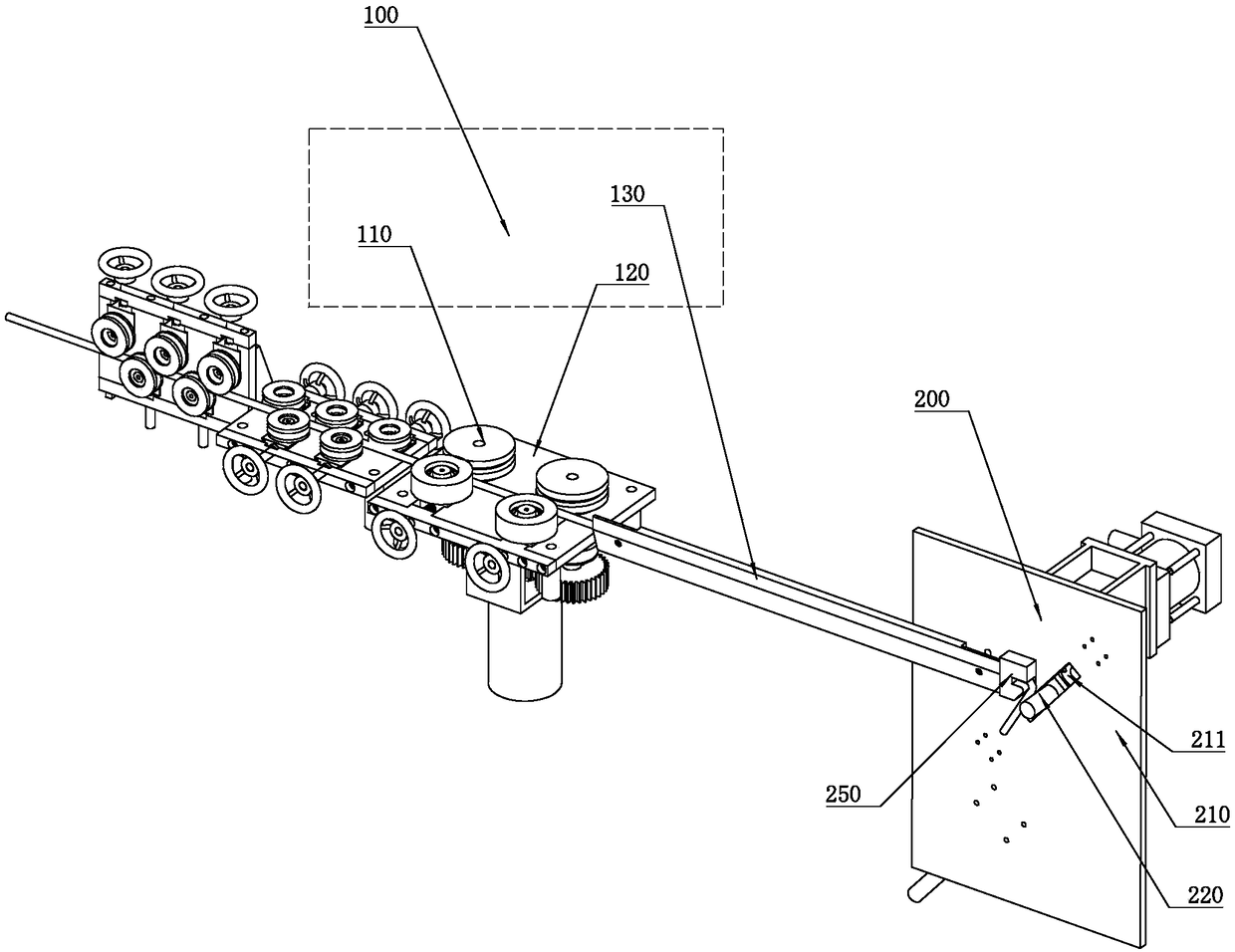
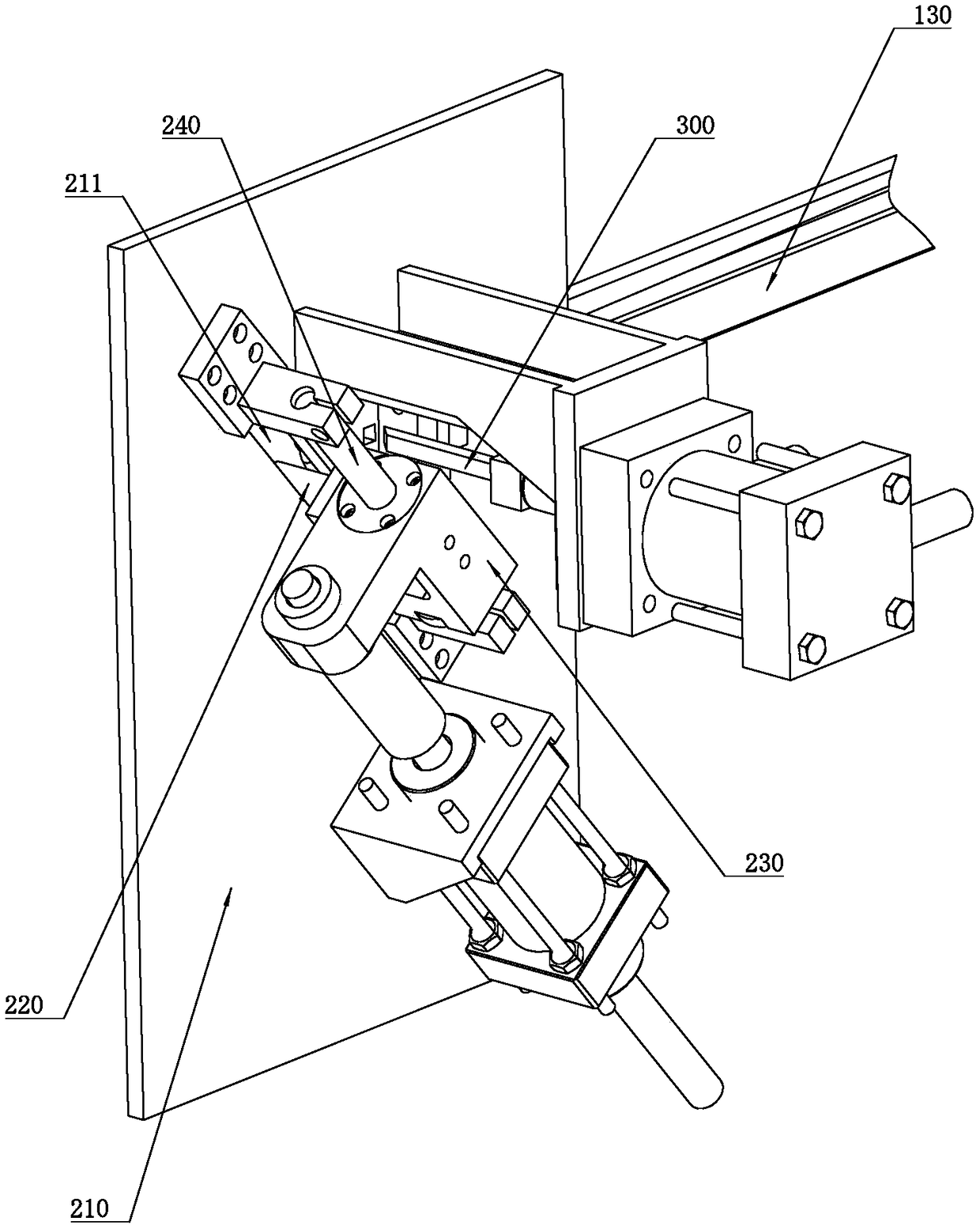
[0018] refer to Figure 1 to Figure 2 , a steel bar bending machine of the present invention includes a conveying device 100 and a bending mechanism 200, the bending mechanism 200 is arranged at the discharge end of the conveying device 100, and the bending mechanism 200 includes a backing plate 210, a fixed block 250, bending knife 220 and oil cylinder; the backing plate 210 abuts against the side of the reinforcing bar, the fixing block 250 is fixed on the backing plate 210, and the fixing block 250 is provided with a through hole for inserting the reinforcing bar, through The upper surface and / or the lower surface of the discharge end of the hole is arranged in an arc shape, and the bending knife 220 is inserted in the backing plate 210 and abuts against the surface of the steel bar, and the bending knife 220 can slide in the steel bar and drive the steel bar to cooperate. The arc-shaped discharge end of the hole is bent, and the bending knife 220 is driven to slide by an o...


PUM


Abstract

The invention discloses a steel bar bending machine. The steel bar bending machine comprises a conveying device and a bending mechanism. The bending mechanism comprises a cushion plate, a fixed block,a bending knife and an oil cylinder. The cushion plate is jointed with the side of steel bars in an abutting mode. The fixed block is fixedly arranged on the cushion plate. The fixed block is provided with through holes where the steel bars are inserted. The upper surface and/or the lower surface of the discharge end of the through-holes and/is arranged in an arc shape. The bending knife penetrates through the cushion plate and is jointed with surfaces of the steel bars in an abutting mode. The bending knife can slide in the steel bars and drive the steel bars to be bent matching the arc-shaped discharge end of the through holes. The bending knife is driven to slide by the oil cylinder. The stroke of the oil cylinder can be adjusted. The former method that a stepping motor is used to control a rotation angle of a bending machine to adjust a bending angle is omitted, and by changing the stroke of the oil cylinder, the displacement of the bending knife jointed with the steel bars in theabutting mode is controlled, so that the bending range of the steel bars is indirectly controlled. The structure of the whole bending machine is simplified, so that it is convenient for users to usein many occasions.

Description

technical field [0001] The invention relates to the field of bending devices, in particular to a steel bar bending machine. Background technique [0002] At present, most of the driving components of hook machines on the market are stepping motors or private motors. Although the precision is high, it is obviously unnecessary to require the angle of the hook of the building beam, and the use of motor drive energy will make the overall product The service life is reduced, and the use of the motor makes the operation of the product more troublesome. Contents of the invention [0003] The present invention aims to solve one of the above-mentioned technical problems in the related art at least to a certain extent. For this reason, the present invention proposes a kind of steel bar bending machine of simplified structure. [0004] The technical solution adopted by the present invention to solve its technical problems is: [0005] A steel bar bending machine includes a conveyi...

Claims


Application Information

Patent Timeline
Patent Type & Authority Applications(China)
IPC IPC(8): B21F1/00
CPCB21F1/00
Inventor 王宏民殷固密王少平王建生康献民李成财李震蒲嘉阳陈晓波谢奕浩陈邦印唐衡云
Owner WUYI UNIV
Why Eureka
Try Eureka