Erecting machine

A technology for assembling machines and pin shafts, which is applied in metal processing, metal processing equipment, manufacturing tools, etc. It can solve problems such as inability to connect, troublesome installation and fixation by staff, and gaps in docking, so as to ensure seamless docking and assembly and fixation Good effect, easy to install and fix

Inactive Publication Date: 2019-02-22
大连巨人北斗高新技术开发有限公司
View PDF8 Cites 0 Cited by
  • Summary
  • Abstract
  • Description
  • Claims
  • Application Information

AI Technical Summary

Problems solved by technology

Since the contribution of the neutral layer to the bending resistance is very small, I-beams are often used instead of square beams in engineering applications, and hollow tubes are used instead of solid columns. The patented design of this invention solves the problem of the inability to assemble I-beams of different specifications. The beam is inconvenient to use, the scope of application is small, the assembly effect is not good, the plates at both ends of the I-beam cannot be docked with the I-beam beam, the installation and fixing of the staff is troublesome, there are gaps in the butt joint, the assembly and fixing effect is not good, and the practicality is poor question

Method used


Image

  • Erecting machine
  • Erecting machine
  • Erecting machine

Examples


Embodiment Construction

[0014] The following will clearly and completely describe the technical solutions in the embodiments of the present invention with reference to the accompanying drawings in the embodiments of the present invention. Obviously, the described embodiments are only some, not all, embodiments of the present invention. Based on the embodiments of the present invention, all other embodiments obtained by persons of ordinary skill in the art without making creative efforts belong to the protection scope of the present invention.

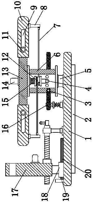
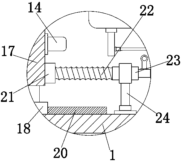
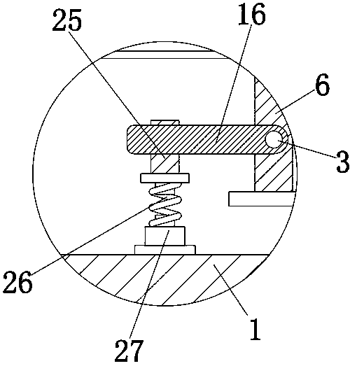
[0015] see Figure 1-3 , the present invention provides a technical solution: an assembly machine, including a base 1 and a pin shaft 5, the base 1 plays the role of supporting and protecting the fixed member, the lower end of the base 1 is fixedly connected with a gasket 2, and the gasket 2 plays the role of The role of supporting and protecting the base 1, the upper end of the base 1 is fixed with a pin shaft 5, the support 6 rotates 180 degrees, and the oth...


PUM


Abstract

The invention discloses an erecting machine. The erecting machine comprises a base and a pin shaft, wherein a screw rod is arranged on the inner wall of a screw nut; the screw nut is in threaded connection with the screw rod; the screw rod penetrates through a push plate; a crank is fixedly connected to the right end of the screw rod; a bracket sleeves the outer wall of the crank; and the lower end of the bracket is fixedly connected with the base. According to the erecting machine disclosed by the invention, through cooperation of a first loop bar and a second loop bar, through cooperation ofa sliding block and a sliding groove, through cooperation of the first loop bar and a connecting bar, through cooperation of a sliding rail and a movable block, through cooperation of the movable block and the push plate, through cooperation of the push plate and the screw nut, through cooperation of the screw nut and the screw rod, through cooperation of the screw rod and a rocker, through cooperation of the rocker and the bracket, through cooperation of the push plate and the movable block, and through cooperation of the movable block and the sliding rail, sheet materials at two ends of anI-shaped beam can be butted with a crossbeam of the I-shaped beam, workers can conveniently realize mounting and fixing, the situation that the butting is gapless is guaranteed, the assembling and fixing effect is good, and the practicality is high.

Description

technical field [0001] The invention relates to the technical field of I-beam assembly, in particular to an assembly machine. Background technique [0002] The I-beam is a rolled iron beam, steel beam or cast steel beam with an I-shaped section; it also refers to a composite beam with an I-shaped section, especially a beam used in a steel structure (such as a steel frame building). Mechanics principle: Place a beam horizontally on two brackets, when the beam is subjected to downward pressure perpendicular to the axis, the beam will bend. Compressive deformation occurs on the upper part of the beam, that is, compressive stress occurs, and the closer to the upper edge, the more severe the compression; tensile deformation occurs on the lower part of the beam, that is, tensile stress occurs, and the closer to the lower edge, the more severe the tension. The middle layer is neither stretched nor compressed, so there is no stress, and this layer is usually called a neutral layer....

Claims


Application Information

Patent Timeline
IPC IPC(8): B23P19/00
CPCB23P19/00
Inventor 包秋菊崔旭刘俊
Owner 大连巨人北斗高新技术开发有限公司
Why Eureka
Try Eureka