Metal surface treatment device

A metal surface treatment and lifting device technology, which is applied in the direction of grinding drive devices, metal processing equipment, machine tools suitable for grinding workpiece planes, etc., can solve the problems of large energy consumption, poor mechanism linkage, and low grinding efficiency, and achieve The effect of increasing stability, increasing linkage, and simple structure

Inactive Publication Date: 2019-02-22
CIXI QICHENG MACHINERY TECH CO LTD
View PDF0 Cites 19 Cited by
  • Summary
  • Abstract
  • Description
  • Claims
  • Application Information

AI Technical Summary

Problems solved by technology

[0002] With the rapid development of science and technology, the scope of application of metals is becoming wider and wider. Some high-tech fields have high requirements for the precision of metal surfaces. Traditional metal surface grinding methods are mostly carried out by manual grinding, and the grinding efficiency is extremely low. , increase the workload of workers, the existing grinding device has a complex structure, poor linkage between mechanisms, low grinding efficiency, consumes a lot of energy, poor stability of the device during operation, and affects the grinding effect

Method used


Image

  • Metal surface treatment device
  • Metal surface treatment device
  • Metal surface treatment device

Examples


Embodiment Construction

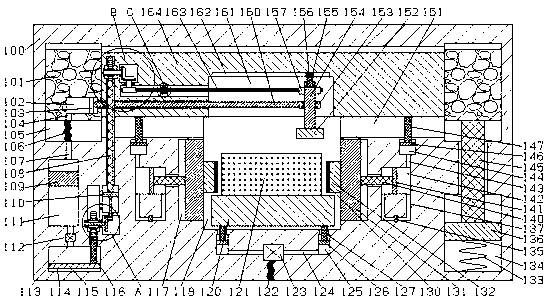
[0016] Combine below Figure 1-5 The present invention is described in detail, and for convenience of description, the orientations mentioned below are now stipulated as follows: figure 1 The up, down, left, right, front and back directions of the projection relationship itself are the same.

[0017] refer to Figure 1-5, a metal surface treatment device according to an embodiment of the present invention, comprising a lathe frame 100 and an operating chamber 118 through which the front and back pass, the upper end wall of the operating chamber 118 is communicated with a lifting chamber 151 extending left and right, and the lifting chamber 151 is provided with a lifting block 164 that can slide up and down, and the left and right sides of the operation chamber 118 are provided with a clamping lifting device, and the clamping lifting device includes a clamping chamber connected to the left and right end walls of the operation chamber 118 117, the end wall of the clamping cham...


PUM


Abstract

The invention discloses a metal surface treatment device. The device comprises a lathe frame and an operating cavity penetrating front and back. A lifting cavity extending left and right is formed inthe upper end wall of the operating cavity in a communicating mode. A lifting block capable of sliding up and down is arranged in the lifting cavity. A clamping lifting device is arranged on the leftand right sides of the operating cavity correspondingly and comprises clamping cavities formed in the left and right end walls of the operating cavity in a communicating mode correspondingly. Hydraulic mechanisms are arranged in the end walls, away from the operating cavity, of the clamping cavities correspondingly, are used for clamping a workpiece in the operating cavity, and drives the liftingblock to move downwards through pressure of hydraulic oil. A height fine adjustment device is arranged in the lower end wall of the operating cavity, comprises hydraulic cavities formed in the lower side of the operating cavity symmetrically in the left-right direction, and is used for precisely adjusting the position of the workpiece through a hydraulic machine. The metal surface treatment deviceis simple in structure, the operating linkage of the device is improved through normal running fit of mechanisms, operation is simplified, energy is saved, the operating stability of the device is guaranteed, and the grinding efficiency is improved.

Description

technical field [0001] The invention relates to the technical field of metal processing, in particular to a metal surface treatment device. Background technique [0002] With the rapid development of science and technology, the scope of application of metals is becoming wider and wider. Some high-tech fields have high requirements for the precision of metal surfaces. Traditional metal surface grinding methods are mostly carried out by manual grinding, and the grinding efficiency is extremely low. , increase the workload of the workers, the existing grinding device has complex structure, poor linkage between mechanisms, low grinding efficiency, consumes a lot of energy, poor stability of the device during operation, and affects the grinding effect. Contents of the invention [0003] The object of the present invention is to provide a metal surface treatment device for overcoming the above-mentioned defects in the prior art. [0004] A metal surface treatment device accordi...

Claims


Application Information

Patent Timeline
Patent Type & Authority Applications(China)
IPC IPC(8): B24B7/10B24B41/06B24B47/22B24B41/02
CPCB24B7/10B24B41/02B24B41/06B24B47/22
Inventor 蔡俊杰
Owner CIXI QICHENG MACHINERY TECH CO LTD
Why Eureka
Try Eureka