A damping pilot valve sleeve control on-off valve

A pilot valve sleeve and pilot valve technology, applied in servo motor components, mechanical equipment, fluid pressure actuators, etc., can solve problems such as the inability to overcome the hydraulic force to push the valve core, increase the volume of the switch valve, and reduce the reliability of the valve. , to achieve the effect of improving the ability to resist external disturbances, reducing the specification size, weight and installation size

Active Publication Date: 2020-09-22
温州大学苍南研究院
View PDF8 Cites 0 Cited by
  • Summary
  • Abstract
  • Description
  • Claims
  • Application Information

AI Technical Summary

Problems solved by technology

For fluid control valves with medium and large flow rates, since the hydraulic force acting on the valve core is too large when the valve core is opened, it is still impossible to overcome the hydraulic force to push the valve core simply by increasing the volume of the electromagnetic drive device.
So the current technology is: use a small electromagnetic switch valve, generally 6-way channel, as the pilot stage to control the pressure of the left and right chambers of the spool, and realize the use of hydraulic power to push the spool, thus solving the problem of reversing valves with large flow rates However, this technology not only increases the volume of the switch valve, but also increases the cost. The superposition of the two valves also increases the complexity of the valve and reduces the reliability of the valve.

Method used


Image

  • A damping pilot valve sleeve control on-off valve
  • A damping pilot valve sleeve control on-off valve
  • A damping pilot valve sleeve control on-off valve

Examples


Embodiment 1

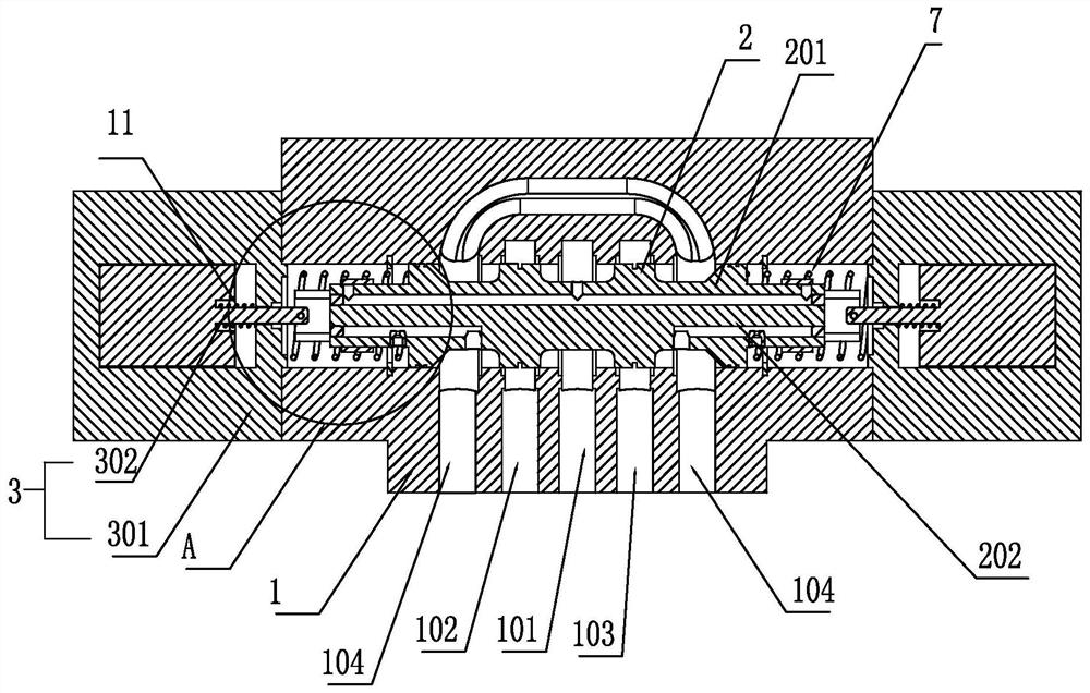
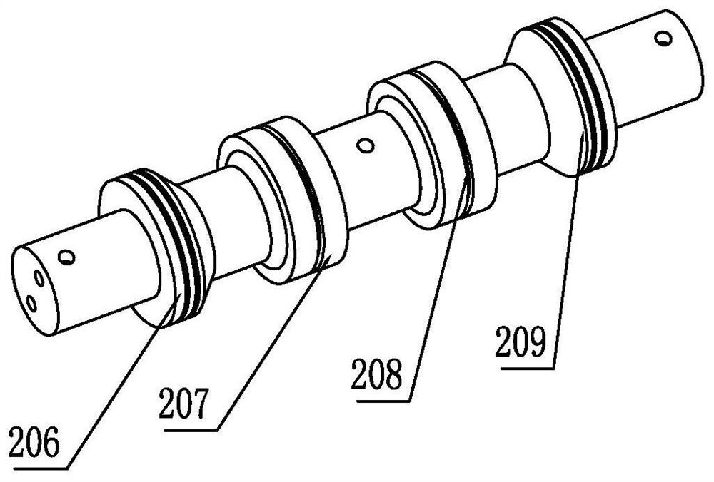
[0032] Such as figure 1 As shown, a damping pilot sleeve control on-off valve includes a valve body 1 and a main valve core 2. The valve body 1 is provided with a high-pressure oil inlet 101, a first control oil port 102, and a second control oil port. 103. The two low-pressure oil outlets 104 can be at zero pressure, the two low-pressure oil outlets 104 are set on both sides, the high-pressure oil inlet 101 is set in the middle, and the first control oil port 102 and the second control oil port 103 are respectively set Between the two low-pressure oil outlets 104 and the high-pressure oil inlet 101, such as figure 2As shown, the main valve core 2 is provided with a first protruding ring 206, a second protruding ring 207, a third protruding ring 208, and a fourth protruding ring 209 in the circumferential direction, and the first protruding ring 206 and the fourth protruding ring 209 are located at two The end and the dynamic sealing cooperation with the valve body 1 can imp...

Embodiment 2

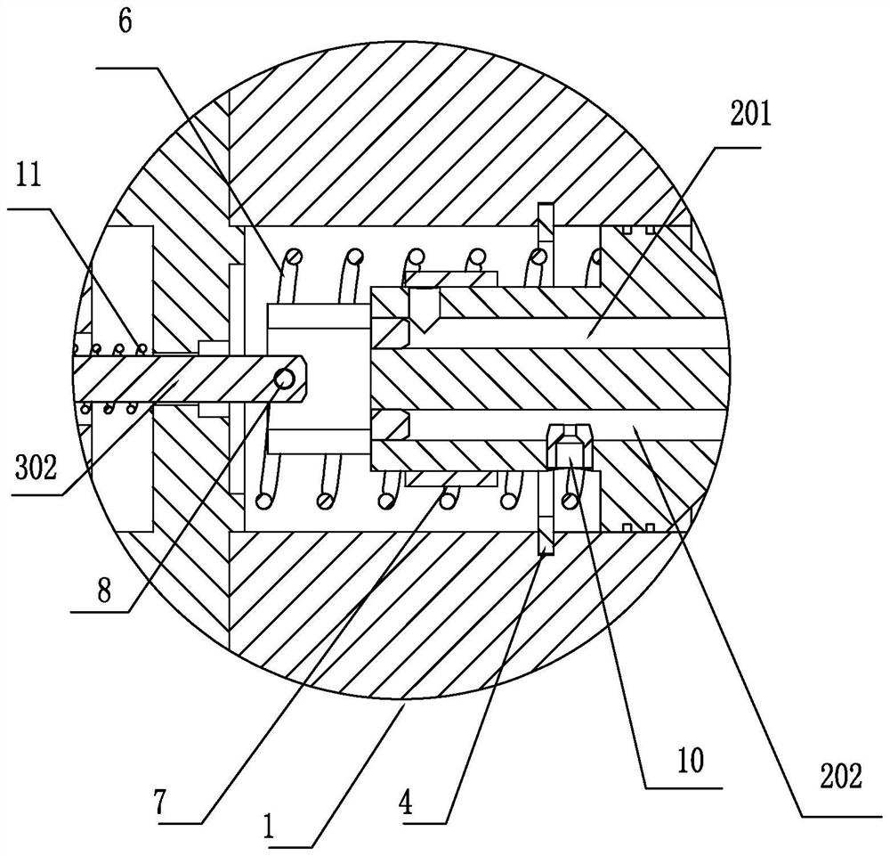
[0043] The difference from Embodiment 1 is that when the electromagnet 301 is energized, the electromagnetic armature 302 is rotated, and the pilot valve sleeve 7 includes a cylindrical main body 701 adapted to the outer periphery of the main valve core. The cylindrical main body 701 is provided with a through hole 703, and the rotation of the electromagnetic armature 302 drives the pilot valve sleeve 7 to rotate axially relative to the main valve core 2 so that the through hole 703 communicates with or staggers the oil inlet passage 201 so that Block the oil inlet passage 201.

[0044] When the electromagnet is not energized, the oil inlet channel 201 is closed, so the hydraulic pressure at both ends of the main valve core is low pressure. The second position where the oil port 103 and the low-pressure oil outlet 104 are separated from each other;

[0045] When the left electromagnet is energized, the left pilot valve sleeve 7 rotates so that the left oil inlet passage 201 i...

Embodiment 3

[0049] Such as Figure 7 As shown, an on-off valve controlled by an inflow damping pilot valve sleeve includes a valve body 1 and a main valve core 2. The valve body 1 is provided with a high-pressure oil inlet 101, a first control oil port 102, and a second control oil port. The port 103 and the two low-pressure oil outlets 104 can be at zero pressure, the two low-pressure oil outlets 104 are arranged on both sides, the high-pressure oil inlet 101 is arranged in the middle, and the first control oil port 102 and the second control oil port 103 are respectively Set between the two low-pressure oil outlets 104 and the high-pressure oil inlet 101, such as figure 2 As shown, the main valve core 2 is provided with a first protruding ring 206, a second protruding ring 207, a third protruding ring 208, and a fourth protruding ring 209 in the circumferential direction, and the first protruding ring 206 and the fourth protruding ring 209 are located at two The end and the dynamic se...


PUM


Abstract

The invention belongs to the field of fluid transmission and control, and in particular, relates to a damping pilot valve sleeve control switching valve. The damping pilot valve sleeve control switching valve comprises a valve body and a main valve element; driving devices are arranged at two ends of the valve body; an adjusting cavity is formed between the driving devices and the main valve element; an oil inlet channel communicating with the adjusting cavity and an oil outlet channel communicating with the adjusting cavity are arranged in the main valve element; a fixed damper is arranged inthe oil outlet channel; a pilot valve sleeve is arranged outside the main valve element; and through driving of the pilot valve sleeve, the hydraulic pressure of the adjusting cavity on one side is changed to form a hydraulic difference so as to shift the main valve element. The pilot control switching valve has the following advantages: (1) the main valve element is driven by hydraulic force, not directly driven by electromagnetism, so that the driving force is greatly increased; (2) the pilot valve sleeve is designed in the valve body to greatly reduce the size; and (3) the pilot valve sleeve is designed to control the pressure of control cavities at two ends of a main valve; and the flow needed by piloting is lower, so that the driving force for driving the pilot valve sleeve is lower,the size of an electromagnetic driving device is further reduced, and meanwhile, the purposes of energy conservation and emission reduction are achieved.

Description

technical field [0001] The invention belongs to the field of fluid transmission and control, and in particular relates to a damping pilot valve sleeve control on-off valve. Background technique [0002] Fluid control valves, especially hydraulic valves, play the role of controlling flow, pressure and switching oil circuits. For example, the electromagnetic switch valve plays the role of controlling the flow and switching the oil circuit; the electromagnetic switch valve is divided into a single-stage valve direct-acting valve and a two-stage valve pilot control valve according to the flow capacity. In the industry standard, the single-stage valve direct-acting valve is divided into 6 passages and 10 passages; the two-stage valve pilot control valve is divided into 16, 25, 32... The larger the passage number, the larger the valve volume, The flow capacity is also greater. [0003] The fluid switch control valve used for small flow is generally in the form of a single-stage ...

Claims


Application Information

Patent Timeline
Patent Type & Authority Patents(China)
IPC IPC(8): F15B13/02
CPCF15B13/021
Inventor 任燕汤何胜向家伟周余庆钟永腾蒋勇英孙维方
Owner 温州大学苍南研究院
Why Eureka
Try Eureka