Center valve bush with cam shaft lubricating structure

A technology of lubricating structure and central valve, applied in the direction of lubricating oil control valve, valve housing structure, lubricating parts, etc., can solve the problems of low oil pressure, unable to meet the lubrication requirements of hollow camshaft, etc., to improve the service life and use effect Effect

Pending Publication Date: 2019-02-22
宁波太平洋电控系统有限公司 +1
View PDF0 Cites 0 Cited by
  • Summary
  • Abstract
  • Description
  • Claims
  • Application Information

AI Technical Summary

Problems solved by technology

[0003] When the traditional mid-mounted central valve adjusts the phaser, in the process of oil circuit switching, the excess oil will flow out through the oil discharge port at the central end to lubricate the camshaft (non-hollow camshaft), because the oil discharge port flows out The low oil pressure of the engine cannot meet the lubrication requirements of the hollow camshaft

Method used


Image

  • Center valve bush with cam shaft lubricating structure
  • Center valve bush with cam shaft lubricating structure
  • Center valve bush with cam shaft lubricating structure

Examples


Embodiment Construction

[0021] The present invention is described in further detail now in conjunction with accompanying drawing. These drawings are all simplified schematic diagrams, which only illustrate the basic structure of the present invention in a schematic manner, so they only show the configurations related to the present invention.

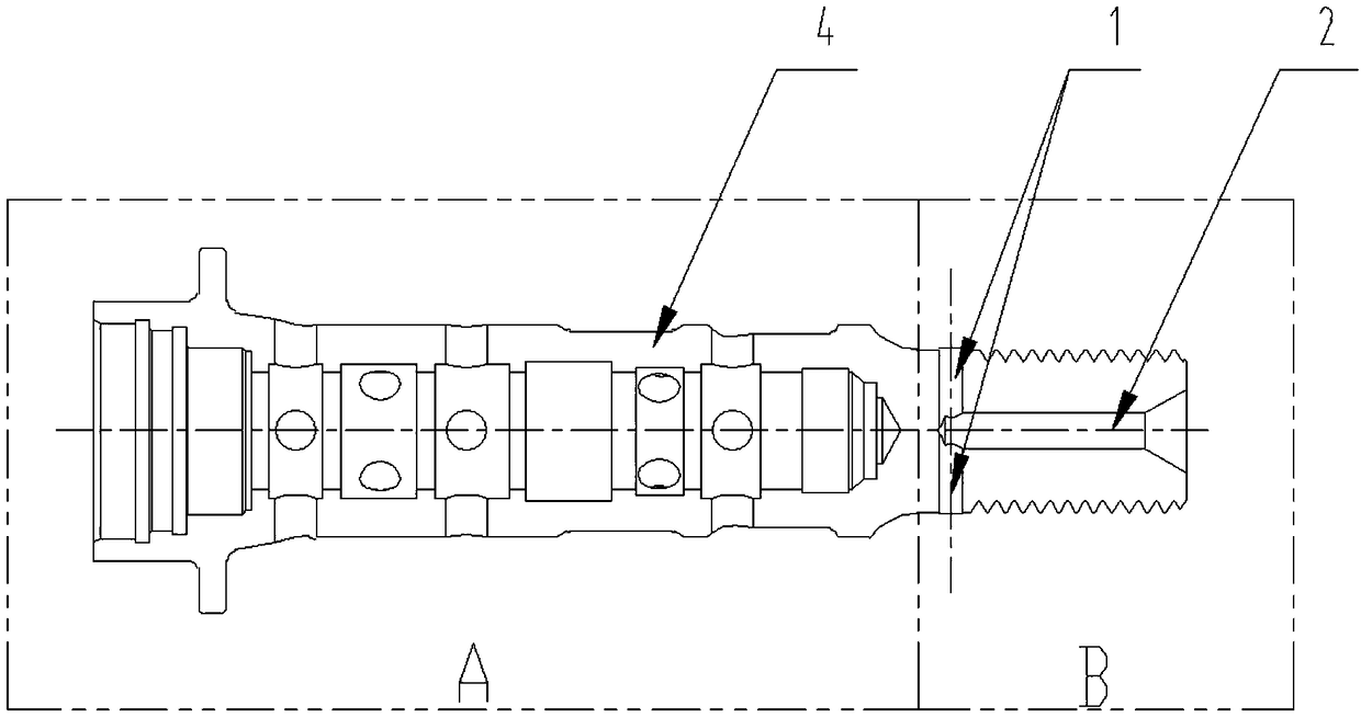
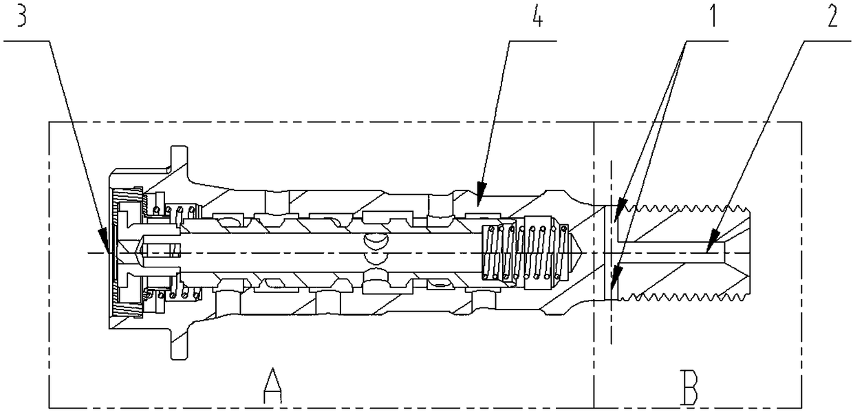
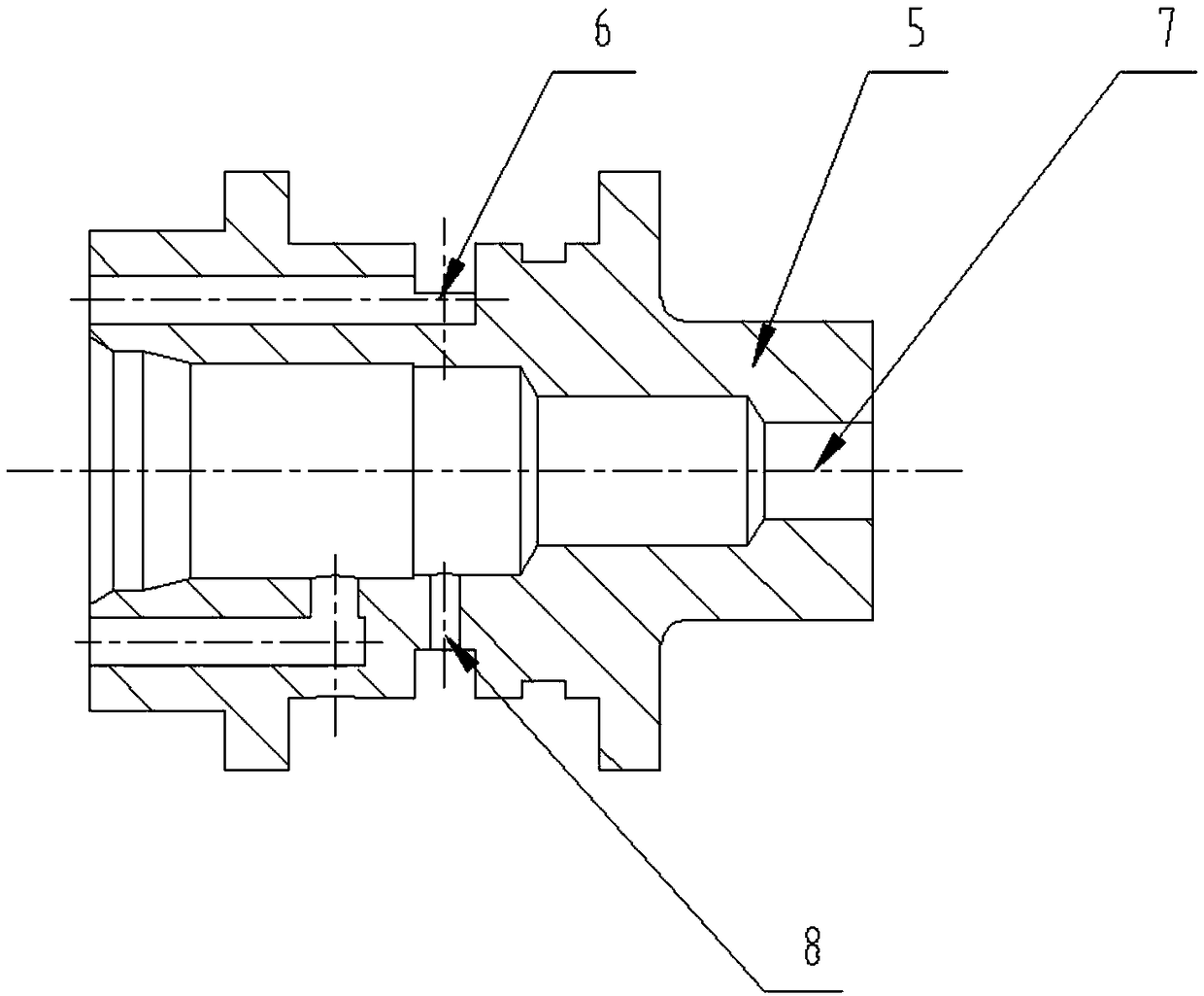
[0022] Such as Figure 1-Figure 3 As shown, a central valve sleeve with a camshaft lubricating structure includes a central valve sleeve body 4, the end of the central valve sleeve body 4 is provided with a camshaft joint 5, and the central valve sleeve body 4 A camshaft actuator is arranged inside, and the end of the central valve sleeve body 4 is provided with a central valve lubricating oil inlet 1 and a central valve lubricating oil outlet 2, and the central valve lubricating oil inlet 1 is set on the central valve valve The outer periphery of the end of the sleeve body 4, the central valve lubricating oil outlet 2 is inside the end of the central valve s...


PUM


Abstract

The invention discloses a center valve bush with a cam shaft lubricating structure. The center valve bush comprises a center valve bush body. A cam shaft joint is arranged on the end part of the center valve bush, a cam shaft executor is arranged in the center valve body, a center valve lubricating oil inlet and a center valve lubricating outlet are formed in the end part of the center valve body,the center valve lubricating oil inlet is formed in the periphery of the end part of the center valve bush body, the center valve lubricating oil outlet is formed in the end part of the center valvebush body, and the center valve lubricating oil inlet communicates to the center valve lubricating oil outlet. By forming a cam lubricating oil hole independently in the tail end of a conventional center valve bush body, the lubricating demand of the hollow cam shaft can be met, so that the service life of a machine is further prolonged and the using effect of the machine is further improved. Thecenter valve bush is reasonable in design and suitable for being popularized and applied.

Description

technical field [0001] The invention relates to the technical field of an automobile camshaft central valve sleeve, in particular to a central valve sleeve with a camshaft lubricating structure. Background technique [0002] The engine variable valve timing technology is one of the new technologies for energy saving and emission reduction of modern automobiles. It can increase the intake air charge, increase the charge coefficient, and make the combustion more complete, so that the torque and power of the engine can be further improved. The central oil control valve (referred to as the central valve) is the control element of the variable valve timing system, which is responsible for adjusting the direction and rotation angle of the actuator oil circuit. [0003] When the traditional mid-mounted central valve adjusts the phaser, in the process of oil circuit switching, the excess oil will flow out through the oil discharge port at the central end to lubricate the camshaft (n...

Claims


Application Information

Patent Timeline
IPC IPC(8): F16K27/00F16N23/00F01L1/344F01M9/10
CPCF16K27/00F16N23/00F01L2001/34426F01M9/10
Inventor 陈男男朱鹏亮朱云振朱煜黄振宇陈红运徐小凯陶小亮
Owner 宁波太平洋电控系统有限公司
Why Eureka
Try Eureka