Mountain crack monitoring and early warning system and early warning method

A technology of monitoring and early warning, mountain, applied in the field of crack monitoring device, monitoring and early warning system of mountain crack deformation, can solve the problem of high professional quality requirements of operators, monitoring timeliness, economy, operability, and structural reliability. Problems such as balance points, inability to obtain data, etc.

Active Publication Date: 2019-02-22
XIANGTAN UNIV +1
View PDF10 Cites 3 Cited by
  • Summary
  • Abstract
  • Description
  • Claims
  • Application Information

AI Technical Summary

Problems solved by technology

Manual data collection cannot realize all-weather and all-terrain observation, cannot issue disaster warning information in time, and cannot obtain a large amount of data in a short period of time; while the use of high-precision instrument monitoring is mostly expensive, complicated to operate, and requires high professional quality of operators, which seriously restricts The popul

Method used


Image

  • Mountain crack monitoring and early warning system and early warning method
  • Mountain crack monitoring and early warning system and early warning method
  • Mountain crack monitoring and early warning system and early warning method

Examples


Embodiment 1

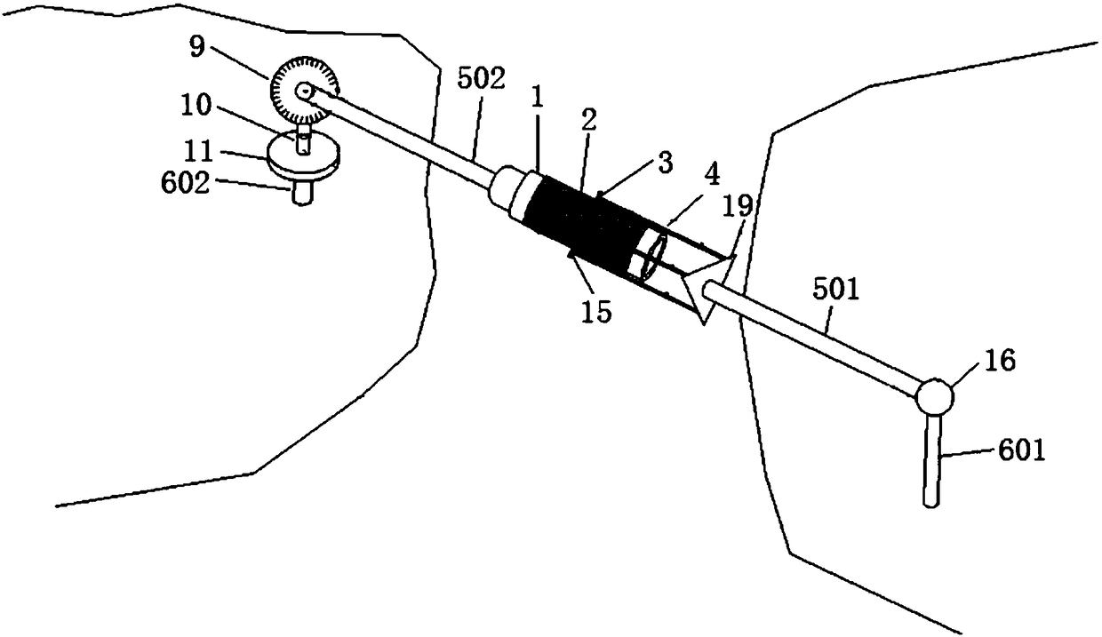
[0131] like figure 1 As shown, a mountain crack monitoring and early warning system, the system includes: an insulating wire barrel 1, a resistance wire 2, a metal slide 3, a metal connecting rod 4, a first non-metallic support rod 501, a second non-metallic support rod 502, A first fixed rod 601 , a second fixed rod 602 , an ammeter 7 , an angle processor 8 , a vertical angle sensor 9 , a pillar 10 , a horizontal angle sensor 11 , and a power supply 12 .

[0132] The resistance wire 2 is wound on the insulating wire barrel 1 . The metal connecting rod 4 is arranged on the periphery of the insulating wire barrel 1 . One end of the metal connecting rod 4 is connected with the metal slide 3 . The metal slide 3 is in contact with the resistance wire 2 on the insulating wire barrel 1 . The first non-metal support rod 501 is connected to the other end of the metal connecting rod 4 and the first fixing rod 601 . The second non-metal support rod 502 connects the end of the insula...

Embodiment 2

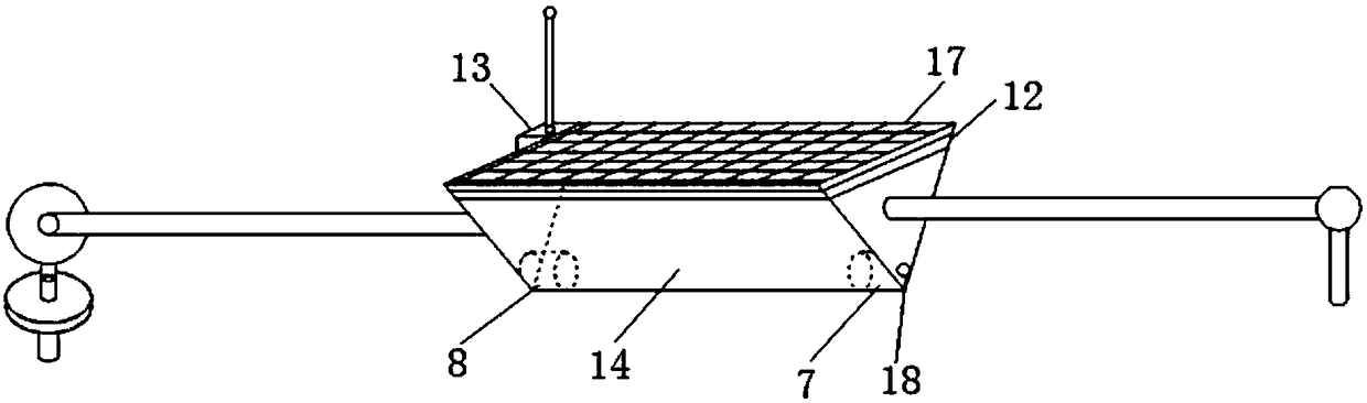
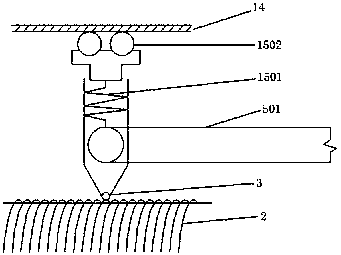
[0137] like figure 2 As shown, Embodiment 1 is repeated, except that the system further includes a wireless signal transmitter 13 . The wireless signal transmitter 13 is connected with the ammeter 7 and the angle processor 8 . The system also includes a housing 14 . The casing 14 wraps around the outside of the sliding rheostat K. The first non-metal support rod 501 and the second non-metal support rod 502 protrude from both ends of the housing 14 respectively. The system also includes a limit pulley 15 . The limit pulley 15 includes a spring 1501 and a pulley 1502 . The spring 1501 connects the pulley 1502 and the metal slide 3 on the sliding rheostat K, and the pulley 1502 is in contact with the inner wall of the housing 14 . The system also includes a steering knuckle 16 . The steering knuckle 16 is disposed at the connection between the first non-metallic support rod 501 and the first fixed rod 601 , and is used for adjusting the angle between the first non-metallic...

Embodiment 3

[0139] Embodiment 2 is repeated, except that the system further includes a protection resistor 18 . The protection resistor 18 is connected in series in the first closed loop. The system also includes a tripod mount 19 . The metal connecting rod 4 is connected with the first non-metallic support rod 501 through the triangular fixing bracket 19 .


PUM

PropertyMeasurementUnit
Diameteraaaaaaaaaa
Diameteraaaaaaaaaa

Abstract

The invention provides a mountain crack monitoring and early warning system. The system comprises an insulated wire barrel, a resistance wire, a metal slide sheet, a metal connecting rod, a first non-metal supporting rod, a second non-metallic supporting rod, a first fixing rod, a second fixing rod, a galvanometer, an angle processor, a vertical angle sensor, a support column, a horizontal angle sensor and a power supply. The resistance wire is wound on the insulated wire barrel. One end of the metal connecting rod is connected to the metal slide sheet. The metal slide sheet is contacted withthe resistance wire on the insulated wire barrel. The first non-metal supporting rod is connected to the other end of the metal connecting rod and the first fixing rod. The second non-metallic supporting rod is connected to the end portion of the insulated wire barrel and the vertical angle sensor. The support column is connected to the vertical angle sensor and the horizontal angle sensor. The bottom of the horizontal angle sensor is connected to the second fixing rod. The structure of the monitoring and early warning system is simple and reliable, operation is convenient, sensitivity is high, and a mountain crack displacement and the real-time change of an angle can be effectively monitored.

Description

technical field [0001] The invention relates to a crack monitoring device, in particular to a monitoring and early warning system and early warning method for crack deformation of mountain bodies, and belongs to the field of monitoring and early warning of natural disasters. Background technique [0002] Mountain cracks are one of the causes of landslides, and their consequences seriously threaten the safety of human life and property. Affected by extreme weather in recent years, its hazards have become more prominent. Therefore, it is of great significance to realize all-weather real-time monitoring of mountain crack deformation and to predict and warn possible landslide disasters. [0003] At present, conventional monitoring methods mostly use manual data collection or high-precision instrument monitoring. Manual data collection cannot achieve all-weather and all-terrain observation, cannot issue disaster warning information in time, and cannot obtain a large amount of d...

Claims


Application Information

Patent Timeline
IPC IPC(8): G01B7/02G01B7/30G08B21/10
CPCG01B7/02G01B7/30G08B21/10
Inventor 陈宾毛从财贾古宁龚成
Owner XIANGTAN UNIV
Why Eureka
Try Eureka