Automatic storage battery discharging device with optimized heat dissipation channel and use method

An automatic discharge and heat dissipation channel technology, applied in battery circuit devices, different battery charging, circuit devices, etc., can solve the problem that the discharge device cannot realize the automatic charging and discharging function of the battery, the activation function of the battery, cannot automatically monitor the state of the battery, and cannot meet the requirements And other issues

Pending Publication Date: 2021-10-08
CHINA YANGTZE POWER
View PDF7 Cites 0 Cited by
  • Summary
  • Abstract
  • Description
  • Claims
  • Application Information

AI Technical Summary

Problems solved by technology

[0005] 1. When using a mobile discharge instrument for discharge, the equipment is transported to the side of the battery pack. There is a risk that the reliability of the discharge instrument will decrease due to factors such as multiple transport vibrations. and other major safety hazards;
[0006] 2. When the mobile discharge instrument is working, it cannot automatically monitor the state of the battery, and manual measurement is required, which has a low degree of automation and a large workload;
[0007] 3. The...

Method used


Image

  • Automatic storage battery discharging device with optimized heat dissipation channel and use method
  • Automatic storage battery discharging device with optimized heat dissipation channel and use method
  • Automatic storage battery discharging device with optimized heat dissipation channel and use method

Examples


Embodiment 1

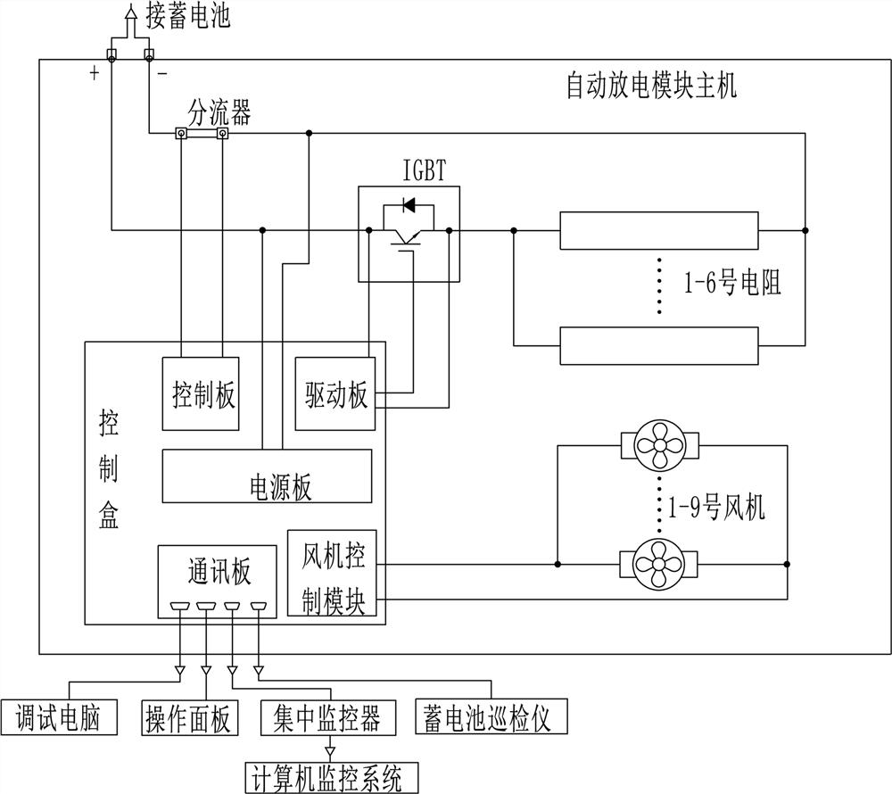
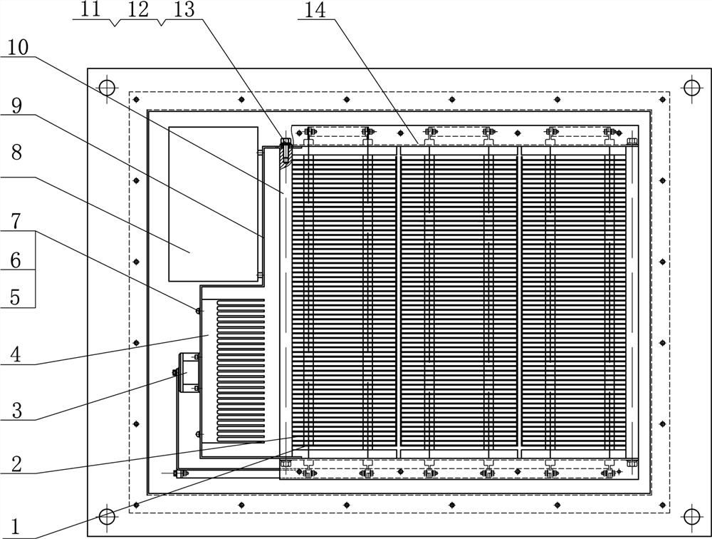
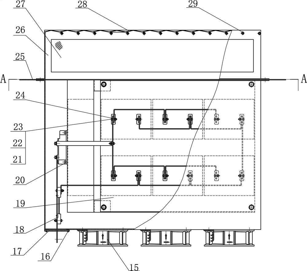
[0039] Such as Figure 1~Figure 7 Among them, an automatic discharge device for storage batteries with optimized heat dissipation channels, including an outer cover 33, a discharge resistor 1 is arranged inside the outer cover 33, and both ends of the discharge resistor 1 are connected to the left side plate 14 and the right side plate 19 of the outer cover 33; the surface of the discharge resistor 1 The heat dissipation fins 2 are inlaid; the heat insulation plate 9 is connected between the left side plate 14 and the right side plate 19 to form a rectangular heat dissipation air duct; the top of the left side plate 14 and the right side plate 19 is connected with an annular top plate 25, and the surface of the top plate 25 is A fixing hole is provided to connect with the DC cabinet.

[0040] Preferably, a top cover 26 is connected above the top plate 25, and the side surface of the top cover 26 is provided with cooling holes, and the surface of the cooling holes is connected ...

Embodiment 2

[0048] Preferably, the above-mentioned method for using an automatic battery discharge device with optimized heat dissipation channels includes the following steps:

[0049] S1, remove the top cover plate of the original DC panel, install the discharge device on the top of the DC panel as a whole, the outer cover 33 is located in the DC panel, and the top plate 25 is connected and fixed to the top edge of the DC panel;

[0050] S2, connect the positive terminal 34 and negative terminal 35 with the discharge switch of the battery pack with cables that meet the requirements; install the operation panel on the front door panel of the cabinet, and use the communication cable to connect the RS485 communication port of the automatic discharge module to the DC system The centralized monitor is connected to the RS485 communication port of the battery inspection instrument, and the parameters are adjusted and then put into operation;

[0051] S3, such as Figure 8 As shown in the figu...


PUM


Abstract

The invention discloses an automatic storage battery discharging device with an optimized heat dissipation channel and a use method. The automatic storage battery discharging device comprises an outer cover, a discharging resistor is arranged in the outer cover, and two ends of the discharging resistor are connected with a left side plate and a right side plate of the outer cover; radiating fins are embedded in the surface of the discharging resistor; a heat insulation plate is connected between the left side plate and the right side plate to form a rectangular heat dissipation air channel; the top of the left side plate and the right side plate is connected with an annular top plate, and the surface of the top plate is provided with fixing holes connected with a DC plate cabinet. According to the device, the discharging current of the storage battery is automatically controlled through the centralized monitor, a large amount of heat generated in the discharging process of the storage battery can be discharged out of the cabinet in time through the specially designed heat dissipation channel, safe and stable operation of the direct-current power supply system is ensured, and economical efficiency and cost are taken into consideration at the same time.

Description

technical field [0001] The invention belongs to the technical field of storage battery maintenance for DC power supply systems, and in particular relates to an automatic discharge device for storage batteries with optimized cooling channels and a use method. Background technique [0002] In the event of a power supply failure, the battery plays an extremely important role as a backup power supply that can continue to provide operating power for equipment such as relay protection devices. There are many factors that affect the life of the battery. Regular testing and maintenance are required to ensure that the battery capacity meets the system requirements and avoid huge economic losses caused by equipment malfunction or refusal to operate. [0003] The regular inspection and maintenance of the battery is mainly the nuclear capacity test of the battery. The charging of the storage battery is completed by the charging device, which is the basic configuration of the DC power s...

Claims


Application Information

Patent Timeline
IPC IPC(8): H02J7/00H01M10/613H01M10/6554H01M10/6563
CPCH02J7/0063H02J7/00714H02J7/0042H02J7/0047H01M10/613H01M10/6554H01M10/6563Y02E60/10
Inventor 孙晓波万和勇陈玉皎
Owner CHINA YANGTZE POWER
Why Eureka
Try Eureka