
On-site monitoring method and device of power facilities

A power facility and on-site monitoring technology, applied in the power field, can solve problems such as waste of personnel resources, slow processing speed, and failure to detect equipment failures in time, so as to avoid false alarms and missed alarms and reduce losses.

Inactive Publication Date: 2019-02-22
国网河南省电力公司孟州市供电公司 +1
View PDF5 Cites 7 Cited by
  • Summary
  • Abstract
  • Description
  • Claims
  • Application Information

AI Technical Summary

Problems solved by technology

[0002] In the traditional monitoring of power facilities, detection equipment is usually used to detect the status of power facilities, and then the detected data is sent to the control processing terminal for processing to monitor the status of power facilities. Due to the number of detection devices installed in each power facility There are many, and the number of power facilities is also large, so the amount of data received by the control processing end is large, and the corresponding processing speed will be slow, which is not conducive to the rapid monitoring of the status of power facilities; Regularly inspect and maintain the power equipment, but this often fails to find some faults in the equipment in time, and does not achieve the effect of real-time monitoring of power equipment, and regular inspections will also cause unnecessary waste of personnel resources

Method used


Image

  • On-site monitoring method and device of power facilities
  • On-site monitoring method and device of power facilities

Examples


Embodiment Construction

[0027] In order to make the technical means, creative features, goals and effects achieved by the present invention easy to understand, the present invention will be further elaborated below in conjunction with specific embodiments:

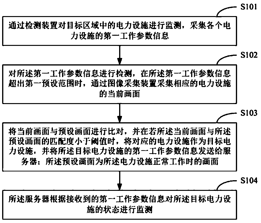
[0028] figure 1 The implementation process of the on-site monitoring method for electric facilities provided by Embodiment 1 of the present invention is shown, and the details are as follows:

[0029] In step S101, the electric facilities in the target area are monitored by the detection device, and the first working parameter information of each electric facility is collected.

[0030] In this embodiment, the detection device is a device capable of detecting the operating parameters of the power facility, such as a sensor; the detection device can be arranged inside and / or outside the power facility, and one power facility corresponds to at least one detection device, and different power facilities The corresponding detection devices are differ...


PUM


Abstract

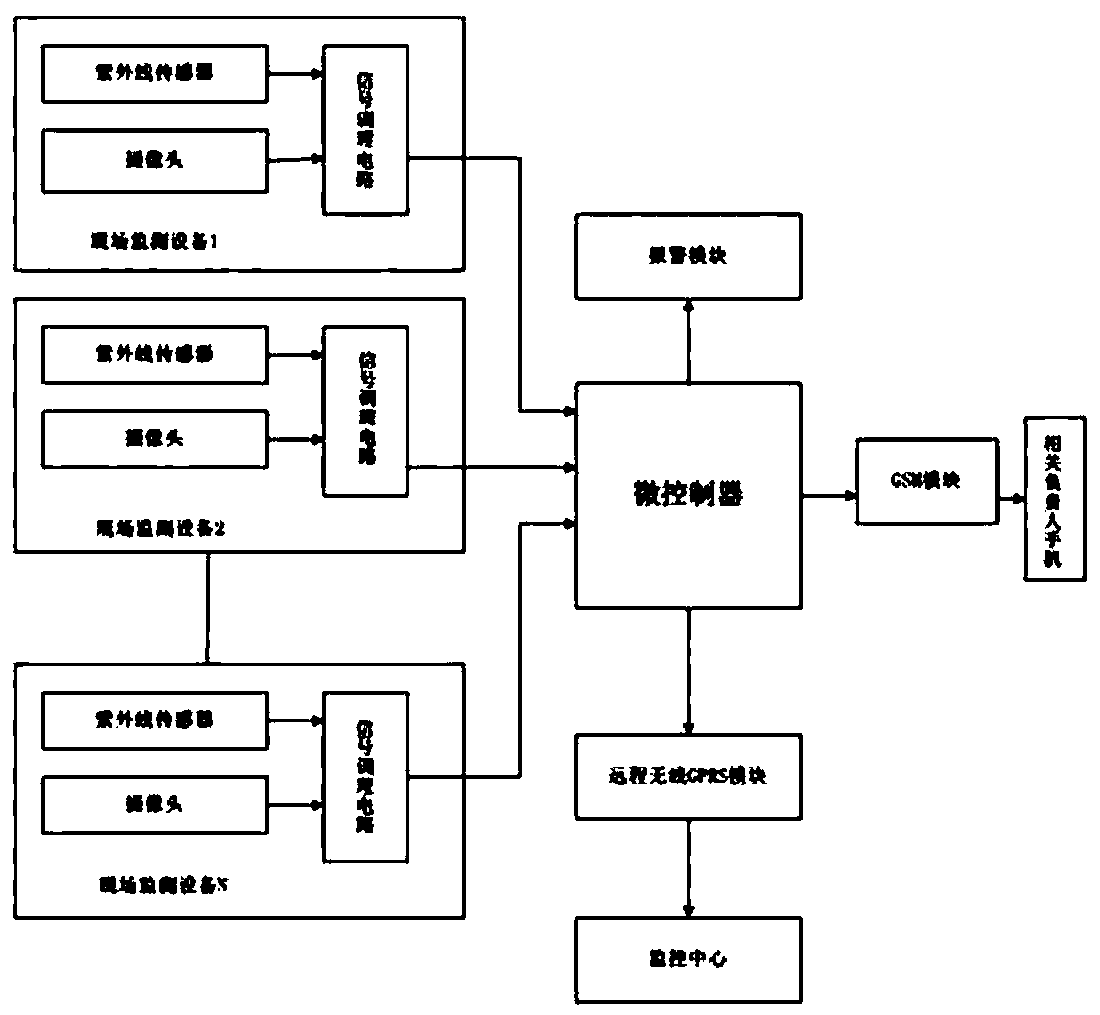
The invention discloses an on-site monitoring method and device of power facilities. The device comprises an on-site monitoring device, a micro controller, an alarm module, a remote wireless GPRS module, a monitoring center and a GSM module. The on-site monitoring device includes an ultraviolet sensor, a camera and a signal conditioning circuit. Full-cover area-division power equipment detection is realized, so that an effect of nipping a problem in the bud is realized and the losses caused by faults are reduced. On the basis of combination of a video image and partial discharge detection, visual and intelligent effects are realized and a fault location and cause can be discovered timely. The power equipment can be monitored remotely; and the special requirements of power equipment condition monitoring and equipment maintenance can be met. When a fault occurs, alarming is carried out automatically and the staff member is informed timely by the short message, so that false alarming andmissing alarming are avoided and the operation becomes convenient and rapid.

Description

technical field [0001] The invention belongs to the field of electric power technology, and in particular relates to a method and device for on-site monitoring of electric power facilities. Background technique [0002] In the traditional monitoring of power facilities, detection equipment is usually used to detect the status of power facilities, and then the detected data is sent to the control processing terminal for processing to monitor the status of power facilities. Due to the number of detection devices installed in each power facility There are many, and the number of power facilities is also large, so the amount of data received by the control processing end is large, and the corresponding processing speed will be slow, which is not conducive to the rapid monitoring of the status of power facilities; Regularly inspect and maintain the power equipment, but it is often impossible to find some faults in the equipment in time, and the effect of real-time monitoring of t...

Claims


Application Information

Patent Timeline
IPC IPC(8): G05B19/042
CPCG05B19/0428G05B2219/24024
Inventor 孙恒程爱武杨梦姣周渭东王建卓权继红柴红艳杜太山李杰王良
Owner 国网河南省电力公司孟州市供电公司
Learn More