
Display panel and display device

A technology for display panels and display areas, applied in the directions of identification devices, static electricity, instruments, etc., can solve the problems of display device performance impact, burning insulation layer, line static electricity accumulation and release, etc., to achieve flexible and convenient line layout, reduce Process difficulty, ensure the effect of the display effect

Active Publication Date: 2021-07-09
SHANGHAI AVIC OPTOELECTRONICS
View PDF0 Cites 0 Cited by
  • Summary
  • Abstract
  • Description
  • Claims
  • Application Information

AI Technical Summary

Problems solved by technology

[0003] However, static electricity is often generated when using the existing technology to make display screens. When the electrostatic charge accumulates to a certain extent in the display screen, it may cause electrostatic breakdown, which will affect the performance of some devices in the display screen, making the defective rate of the display screen has been high
Especially in the process of manufacturing the array substrate, due to the considerable number of lines on the array substrate, in order to reduce the coupling effect between the lines and reduce the difficulty of wiring, the lines are usually arranged in multiple film layers, and the line pattern After forming and stripping the photoresist, the lines of this layer are prone to static electricity accumulation and discharge. At this time, the entire array substrate is not fully formed, the antistatic performance is weak, and the longer lines will generally be released in the direction of its extension. Static electricity, it is very easy to burn out the insulation layer between the lines, so that short circuits, electrostatic breakdown and other adverse conditions often occur between the lines

Method used


Image

  • Display panel and display device
  • Display panel and display device
  • Display panel and display device

Examples


Embodiment Construction

[0031] Various exemplary embodiments of the present invention will now be described in detail with reference to the accompanying drawings. It should be noted that the relative arrangements of components and steps, numerical expressions and numerical values ​​set forth in these embodiments do not limit the scope of the present invention unless specifically stated otherwise.

[0032] The following description of at least one exemplary embodiment is merely illustrative in nature and in no way taken as limiting the invention, its application or uses.

[0033] Techniques, methods and devices known to those of ordinary skill in the relevant art may not be discussed in detail, but where appropriate, such techniques, methods and devices should be considered part of the description.

[0034] In all examples shown and discussed herein, any specific values ​​should be construed as exemplary only, and not as limitations. Therefore, other instances of the exemplary embodiment may have dif...


PUM


Abstract

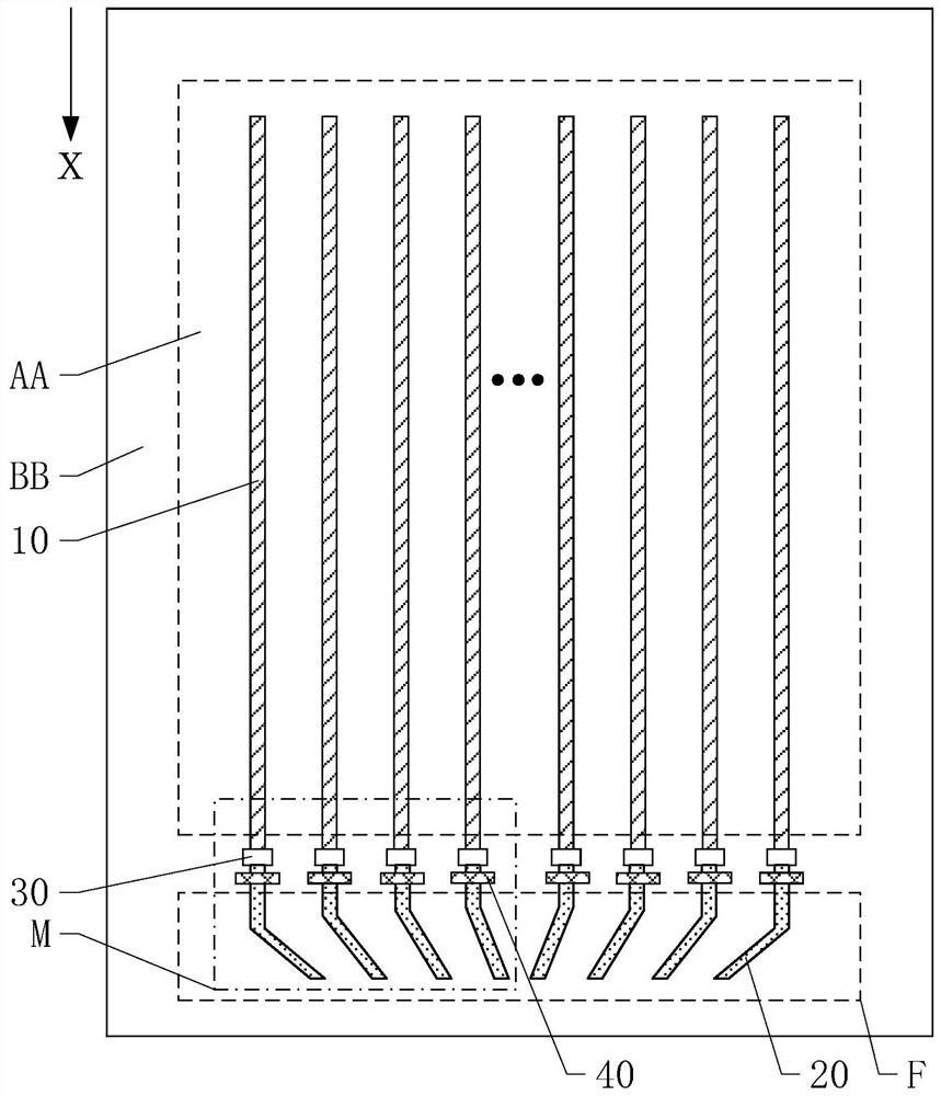
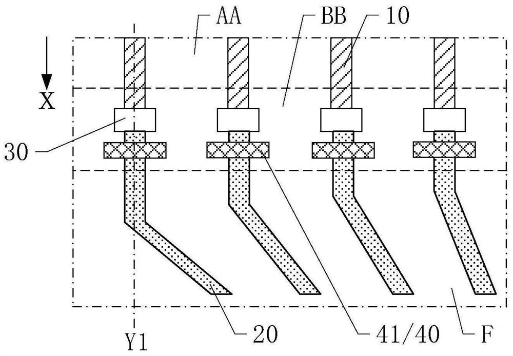
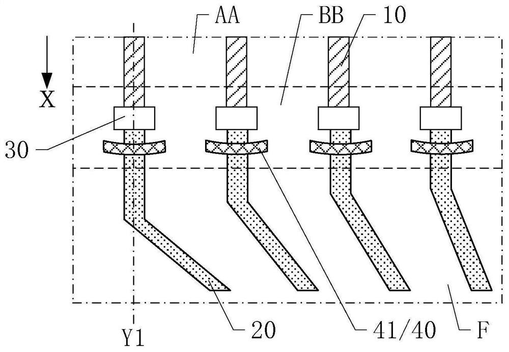
The invention discloses a display panel and a display device, comprising: a display area and a non-display area arranged around the display area; the display area includes a plurality of first signal lines extending along a first direction; the non-display area includes a fan-out area, The fan-out area includes a plurality of first signal connection lines, the first signal connection lines and the first signal lines are arranged in different layers, and the two are electrically connected through a conductive part; at least one first signal line is provided on a side close to the fan-out area The static blocking structure, the static blocking structure and the first signal line are arranged in the same layer; the static blocking structure includes at least one first static blocking part, and the extension line of the first signal line overlaps with the first static blocking part. Compared with the prior art, when the first signal line discharges static electricity in the direction of its extension, the static electricity is first released to the first static blocking part, thereby effectively preventing short circuit and static shock caused by the discharge of static electricity to the surrounding circuits of the first signal line. wear and other bad conditions.

Description

technical field [0001] The present invention relates to the field of display technology, and more particularly, to a display panel and a display device. Background technique [0002] With the rapid development of display technology, the display screen is constantly developing towards the direction of high integration and low cost. From the original cathode ray tube (Cathode Ray Tube, CRT) display screen to the liquid crystal display screen commonly used today, the display screen is in the Integration, production cost and picture quality have all been greatly improved. [0003] However, static electricity is often generated when using the existing technology to make display screens. When the electrostatic charge accumulates to a certain extent in the display screen, it may cause electrostatic breakdown, which will affect the performance of some devices in the display screen, making the defective rate of the display screen It has remained high. Especially in the process of m...

Claims


Application Information

Patent Timeline
Patent Type & Authority Patents(China)
IPC IPC(8): G09F9/00H05F3/00
CPCG09F9/00H05F3/00
Inventor 金慧俊
Owner SHANGHAI AVIC OPTOELECTRONICS
Learn More