
A cable pay-off and cutting device for electric power engineering

A technology of electric power engineering and cutting device, applied in cable installation device, cable installation, cable laying equipment and other directions, can solve the problems of inability to fix cables, heavy weight of winding cables, and increased cable laying tasks.

Active Publication Date: 2020-10-27
STATE GRID CORP OF CHINA +1
View PDF5 Cites 0 Cited by
  • Summary
  • Abstract
  • Description
  • Claims
  • Application Information

AI Technical Summary

Problems solved by technology

[0002] Wires and cables are used to transmit electric (magnetic) energy, information and wire products that realize the conversion of electromagnetic energy. In a broad sense, wires and cables are also referred to as cables for short. In a narrow sense, cables refer to insulated cables, which can be defined as: a collection composed of the following parts ; One or more insulated wire cores, and their respective possible cladding layers, total protective layers and outer sheaths, and cables can also have additional uninsulated conductors. At present, with the development of urban construction, various enterprises The needs of public institutions and residents for communication are also growing rapidly, and the task of laying cables is increasing. The original cable pay-off vehicle, because the weight of the wound cable is very heavy, so it is necessary to release the cable wound on the bobbin. It is a very arduous task, and several people need to drag the cable during the unwinding, and the winding drum will rotate accordingly to release the cable.
[0003] A cable unwinding and cutting device for power engineering disclosed in the Chinese invention patent application publication specification CN201710250964.5, although the cable unwinding and cutting device for electric power engineering can automatically rotate to release the cable, and has a good fixing effect on the cable , and the effect of cutting the cable, and by setting the clamping block and the anti-slip pad, the stability of the device is better. However, the cable setting and cutting device for power engineering is difficult to operate manually and is too dependent on power. Therefore, , Aiming at the above problems, a cable pay-off and cutting device for power engineering is proposed

Method used


Image

  • A cable pay-off and cutting device for electric power engineering
  • A cable pay-off and cutting device for electric power engineering
  • A cable pay-off and cutting device for electric power engineering

Examples


Embodiment Construction

[0019] The following will clearly and completely describe the technical solutions in the embodiments of the present invention with reference to the accompanying drawings in the embodiments of the present invention. Obviously, the described embodiments are only some, not all, embodiments of the present invention.

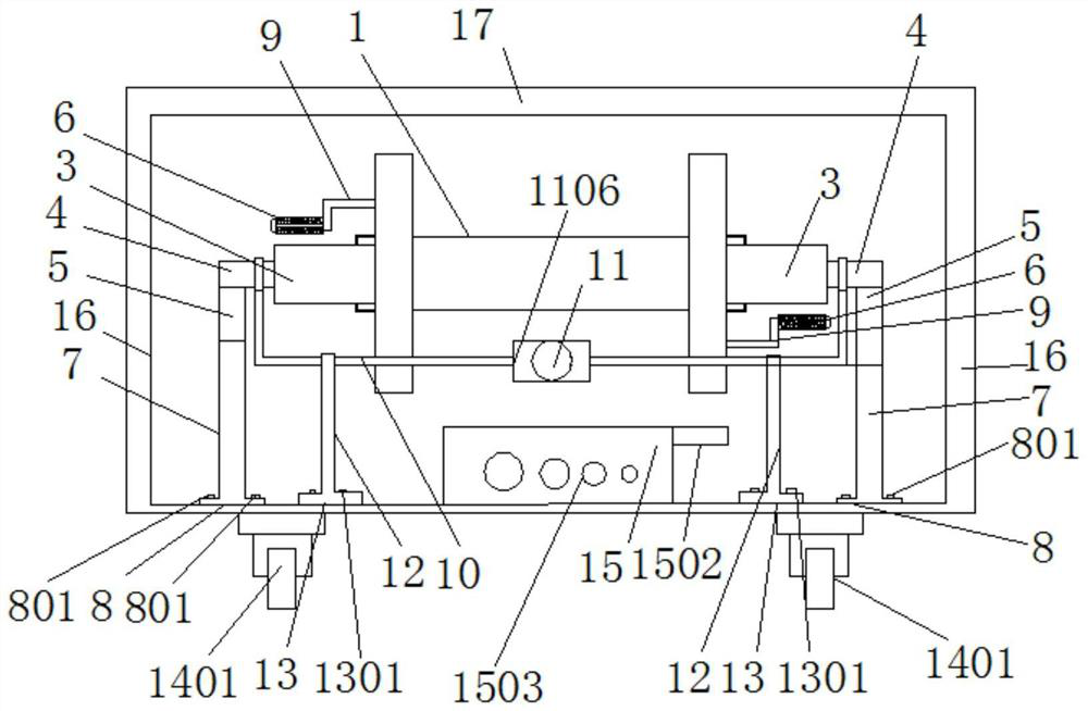
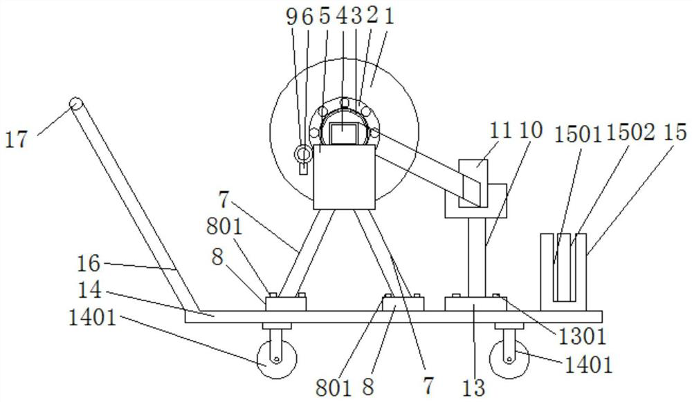
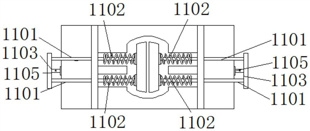
[0020] see Figure 1 to Figure 3 , a cable pay-off and cutting device for electric power engineering, comprising a cable rack 1, the interior of the cable rack 1 is hollow, and both sides of the cable rack 1 are provided with bearings 2, the number of the bearings 2 is two, and the cable rack 1 There is a fixed shaft 3 inside, and through the setting of two handles 9, the fixed shaft 3 and the bearing 2, the cable rack 1 can be rotated more briskly, and the operator can save labor. The middle parts of both sides of the fixed shaft 3 are provided with fixed blocks 4 Through the setting of the shaft and the fixing block 4, the cable rack 1 can be effectively positioned...


PUM


Abstract

The invention discloses a cable paying off cutting device used for electric power engineering. The device includes a cable rack; bearings are disposed on both sides of the cable rack; a fixed shaft isdisposed inside the cable rack; fixed blocks are disposed on the middle on both sides of the fixed shaft; supporting frames are disposed on two ends of the shaft near the fixed blocks; the middle ofthe support frames is fixedly connected with a wire passing device; the top of a bottom plate of a cart is provided with a wire cutting device; and a hand push rod is fixedly connected to one end ofeach of supporting columns away from the bottom plate of the cart. Through arrangement of two handles, the shaft and the bearings, when the cable rack rotates, the cable rack is brisker, and operationpersonnel is more labor-saving; through the arrangement of the shaft and the fixed blocks, the cable rack can be effectively positioned to prevent the occurrence of the phenomenon of the cable rack swaying back and forth; and through the arrangement of four springs, the pressure between clamping blocks is increased, and the purpose of time and labor conservation, simple operation and firm fixation is achieved.

Description

technical field [0001] The invention relates to a cable cutting device, in particular to a cable pay-off and cutting device for electric power engineering, and belongs to the technical field of electric engineering applications. Background technique [0002] Wires and cables are used to transmit electric (magnetic) energy, information and wire products that realize the conversion of electromagnetic energy. In a broad sense, wires and cables are also referred to as cables for short. In a narrow sense, cables refer to insulated cables, which can be defined as: a collection composed of the following parts ; One or more insulated wire cores, and their respective possible cladding layers, total protective layers and outer sheaths, and cables can also have additional uninsulated conductors. At present, with the development of urban construction, various enterprises The needs of public institutions and residents for communication are also growing rapidly, and the task of laying cab...

Claims


Application Information

Patent Timeline
Patent Type & Authority Patents(China)
IPC IPC(8): B65H49/30H02G1/06H02G1/00
CPCB65H49/32B65H2701/34H02G1/005H02G1/06
Inventor 郑韩蓉田颖慧谭俊徐拓沈忱周月乔万付宝李言明邓明华明璇欧亚敏梁海兰崔伟
Owner STATE GRID CORP OF CHINA
Learn More