
A permanent magnet motor rotor structure

A technology of rotor structure and permanent magnet motor, applied in the direction of magnetic circuit shape/style/structure, magnetic circuit rotating parts, magnetic circuit, etc., can solve the problems of weak magnetic field speed expansion ability, large magnetic flux leakage coefficient of tangential structure, Problems such as low utilization rate of permanent magnet materials, to achieve the effect of increasing power density, increasing salient pole ratio, and strengthening mechanical strength

Inactive Publication Date: 2020-05-26
HARBIN UNIV OF SCI & TECH
View PDF8 Cites 0 Cited by
  • Summary
  • Abstract
  • Description
  • Claims
  • Application Information

AI Technical Summary

Problems solved by technology

Since the surface-type rotor is attached to the rotor surface, it has no asynchronous start-up capability, and in the built-in rotor, the single radial structure cannot effectively use the reluctance torque, and the weak-field speed expansion capability is poor, and the magnetic flux leakage coefficient of the tangential structure is relatively low. Large, low utilization rate of permanent magnet material

Method used


Image

  • A permanent magnet motor rotor structure
  • A permanent magnet motor rotor structure
  • A permanent magnet motor rotor structure

Examples


Embodiment Construction

[0022] The following will clearly and completely describe the technical solutions in the embodiments of the present invention with reference to the accompanying drawings in the embodiments of the present invention. Obviously, the described embodiments are only some, not all, embodiments of the present invention. Based on the embodiments of the present invention, all other embodiments obtained by persons of ordinary skill in the art without making creative efforts belong to the protection scope of the present invention.

[0023] In the description of the present invention, it should be understood that the orientations or positional relationships indicated by the terms "upper", "lower", "left" and "right" are based on the orientations and positional relationships shown in the drawings, and are only for convenience of description It does not indicate or imply that the referred part must have a specific orientation and operate in a specific orientation, and thus should not be const...


PUM


Abstract

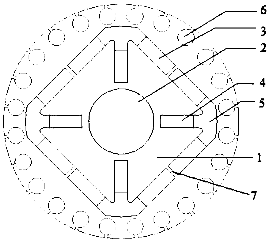
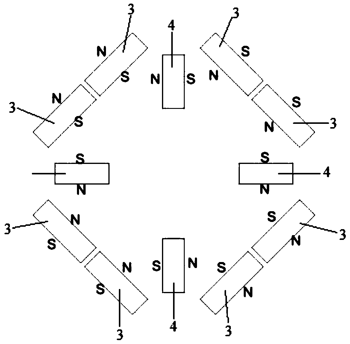
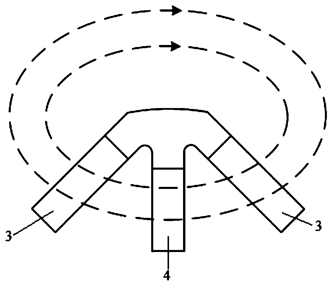
The invention discloses a permanent magnet motor rotor structure. The permanent magnet motor rotor structure includes a rotor core, a rotating shaft and multiple first permanent magnets, second permanent magnets and T-shaped fillers. The rotating shaft is arranged in the middle of the rotor core. Multiple T-shaped filler grooves are arranged along the outer side of the rotating shaft. The two sides of each T-shaped filler groove respectively communicate with two first permanent magnet grooves arranged in tangential directions. The inner side of each T-shaped filler groove communicates with a radially arranged second permanent magnet groove. The first permanent magnets, second permanent magnets and T-shaped fillers correspond to the first permanent magnet grooves, second permanent magnet grooves and T-shaped filler grooves. The polarity of the same sides of the two adjacent first permanent magnets between the two T-shaped fillers is the same, the polarity of the opposite sides of the adjacent first permanent magnet and the second permanent magnet is opposite, and the polarity of the opposite sides of the two adjacent second permanent magnets is the same. The permanent magnet motor rotor structure improves the salient pole rate, makes full use of reluctance torque, expands an operation range of constant power, and improves weak magnetic speed expansion capability.

Description

technical field [0001] The invention relates to the technical field of permanent magnet motors, in particular to a permanent magnet motor rotor structure. Background technique [0002] Traditional permanent magnet synchronous motors are divided into surface rotors and built-in rotors according to the rotor structure, and the built-in rotors are further divided into radial structures and tangential structures. Since the surface-type rotor is attached to the rotor surface, it has no asynchronous start-up capability, and in the built-in rotor, the single radial structure cannot effectively use the reluctance torque, and the weak-field speed expansion capability is poor, and the magnetic flux leakage coefficient of the tangential structure is relatively low. Large, low utilization rate of permanent magnet material. Therefore, it is necessary to improve the rotor structure of the existing asynchronous start permanent magnet synchronous motor. Contents of the invention [0003...

Claims


Application Information

Patent Timeline
Patent Type & Authority Patents(China)
IPC IPC(8): H02K1/27H02K21/46
CPCH02K1/276H02K21/46H02K2213/03
Inventor 陶大军王必成许传一戈宝军
Owner HARBIN UNIV OF SCI & TECH
Learn More