Line scan camera triggering time-sequence synchronization method, line scan camera triggering time-sequence synchronization device, line scan camera triggering time-sequence synchronization equipment and storage medium
A line array camera and timing synchronization technology, applied in the camera field, can solve problems such as image distortion, picture stretching or distortion, image stretching, etc., to achieve the effect of solving image stretching or image distortion, and improving image shooting effect
- Summary
- Abstract
- Description
- Claims
- Application Information
AI Technical Summary
Problems solved by technology
Method used
Image
Examples
Embodiment 1
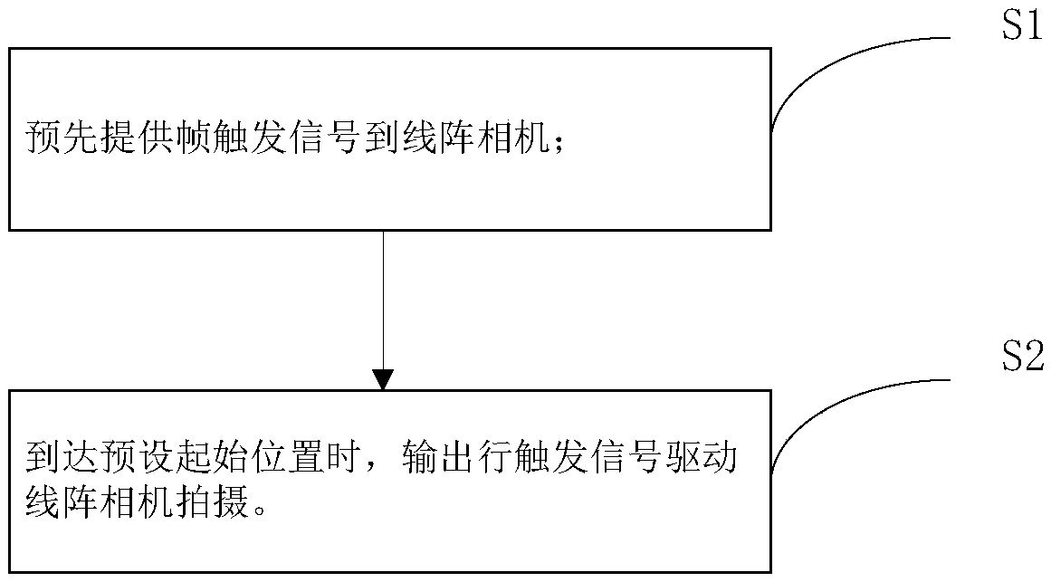
[0031] image 3 It is a schematic flow chart of a line array camera trigger timing synchronization method of the present invention, refer to image 3 , a line array camera trigger timing synchronization method, used in a line array camera scanning system, the line array camera scanning system includes an imaging component for photographing an object to be inspected, a carrier for placing an object to be inspected, and a Y-axis motor. The tool moves along the Y-axis driven by the Y-axis motor, the photographing component includes a line camera, and the method includes steps S1 to S2.
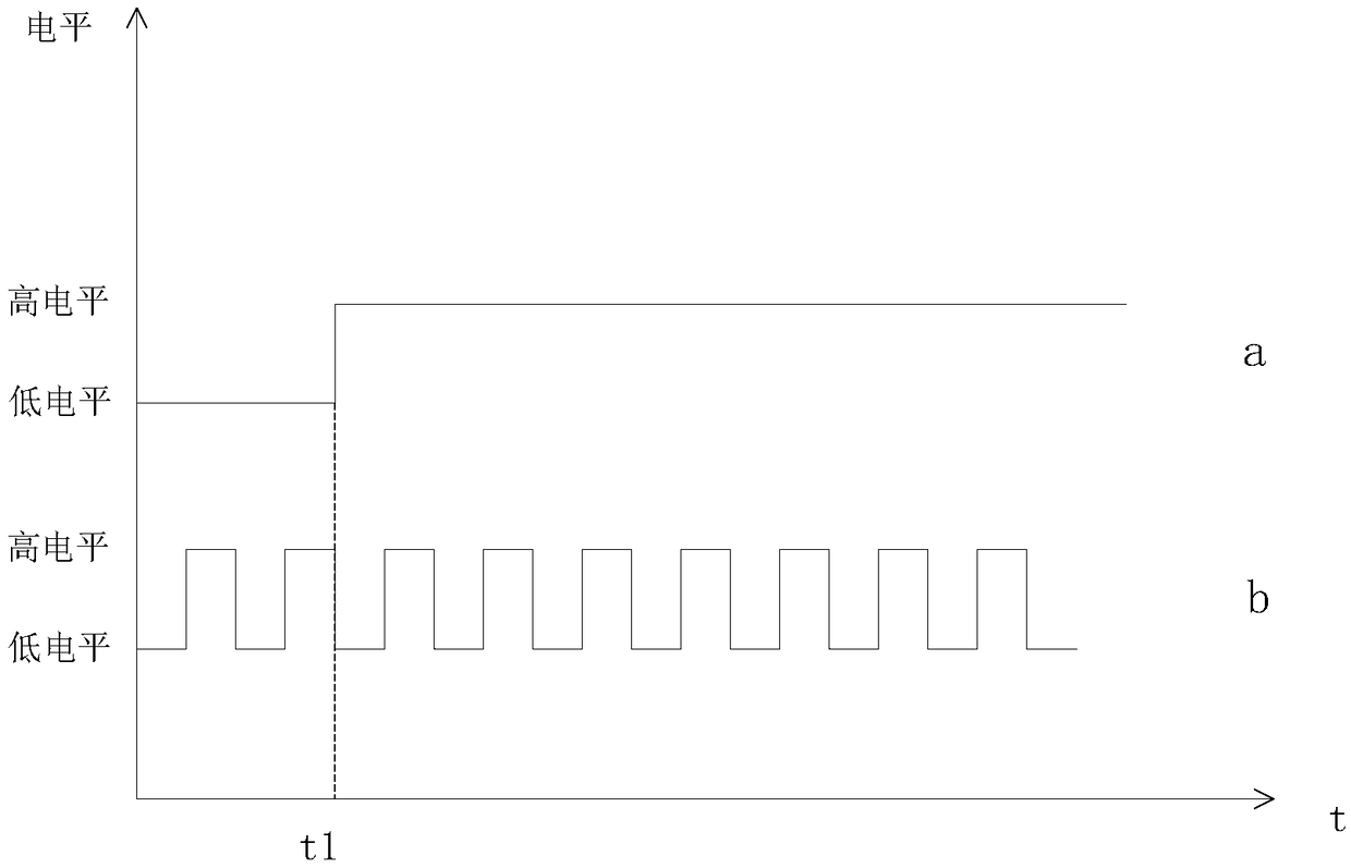
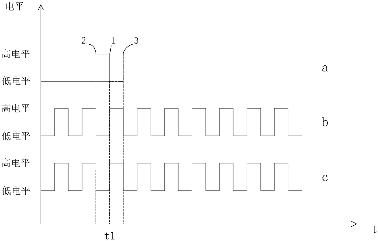
[0032] S1, providing frame trigger signal (high level) to the line scan camera in advance;
[0033] S2, when the preset start position is reached, the line trigger signal is output to drive the line scan camera to shoot.
[0034] Wherein, the starting position is set after the start of the frame trigger signal.
[0035] In this embodiment, the line scan camera scanning system further includes ...
Embodiment 2
[0039] Figure 4 It is a module block diagram of a line array camera trigger timing synchronization device of the present invention, refer to Figure 4 , a line-scan camera trigger timing synchronization device is used in a line-scan camera scanning system. The line-scan camera scanning system includes a shooting part for shooting an object to be detected, a carrier for placing the object to be detected, and a Y-axis motor. The tool moves along the Y-axis driven by the Y-axis motor, the photographing component includes a line camera, and the synchronization device also includes a first trigger module and a second trigger module.
[0040] The first trigger module is used to provide a frame trigger signal (high level) to the line scan camera in advance. In a specific embodiment, the first triggering module is set in the line-scan camera scanning system and connected to the line-scan camera, and the first triggering module is a controller.
[0041] The second trigger module is ...
Embodiment 3
[0047] The embodiment of the present invention also provides a line-scan camera trigger timing synchronization device, including:
[0048] at least one processor; and a memory communicatively coupled to the at least one processor; wherein,
[0049] The memory stores instructions that can be executed by at least one processor, and the instructions are executed by the at least one processor, so that the at least one processor can execute the above-mentioned method for synchronizing trigger timing of line scan cameras.
PUM
 Abstract
Description
Claims
Application Information
 - R&D
- Intellectual Property
- Life Sciences
- Materials
- Tech Scout
- Unparalleled Data Quality
- Higher Quality Content
- 60% Fewer Hallucinations
Browse by: Latest US Patents, China's latest patents, Technical Efficacy Thesaurus, Application Domain, Technology Topic, Popular Technical Reports.
© 2025 PatSnap. All rights reserved.Legal|Privacy policy|Modern Slavery Act Transparency Statement|Sitemap|About US| Contact US: help@patsnap.com


