Servo gluing quantification machine

A technology of gluing and servo electric cylinders, which is applied to coatings and devices for coating liquid on the surface, etc. It can solve the problems of high measurement accuracy of servo push cylinders, long lengths of actuators, and bulky volumes, etc., to improve pressure resistance Stable reliability and service life, long life, small size effect

Inactive Publication Date: 2019-02-26
YANTAI KEPAI INTELLIGENT TECH CO LTD
View PDF8 Cites 3 Cited by
  • Summary
  • Abstract
  • Description
  • Claims
  • Application Information

AI Technical Summary

Problems solved by technology

For the gear pump metering mechanism, the problem is that the metering accuracy is not as high as that of the servo push cylinder, and its accuracy will decrease significantly as time goes on; and for the servo push cylinder metering mechanism currently on the market, the main problems are as follows: 1) Due to Glue is the principle of first-in-last-out, and it is easy to form glue accumulation or residual glue in the glue tank after long-term use; 2) The existing actuator (the actuator integrated with the servo motor, gearbox and ball screw), in In terms of appearance, its disadvantage is that it is bulky and the length of the actuator is too long (limited by the assembly space of the field application); 3) In terms of function, when the reverse speed of the servo motor is greater than the filling speed of the glue in the glue tank, it is easy to There is a problem of vacuum formation in the glue tank; 4) When the piston rod is moved up and down when the O-ring seal is used for sealing, especially under high pressure conditions (138 kg to 350 kg), the service life of this dynamic sealing method is relatively short. Generally, there will be glue leakage between one month and three months (depending on the working conditions on site)

Method used


Image

  • Servo gluing quantification machine
  • Servo gluing quantification machine
  • Servo gluing quantification machine

Examples


Embodiment Construction

[0021] The present invention will be further described below in conjunction with accompanying drawing:

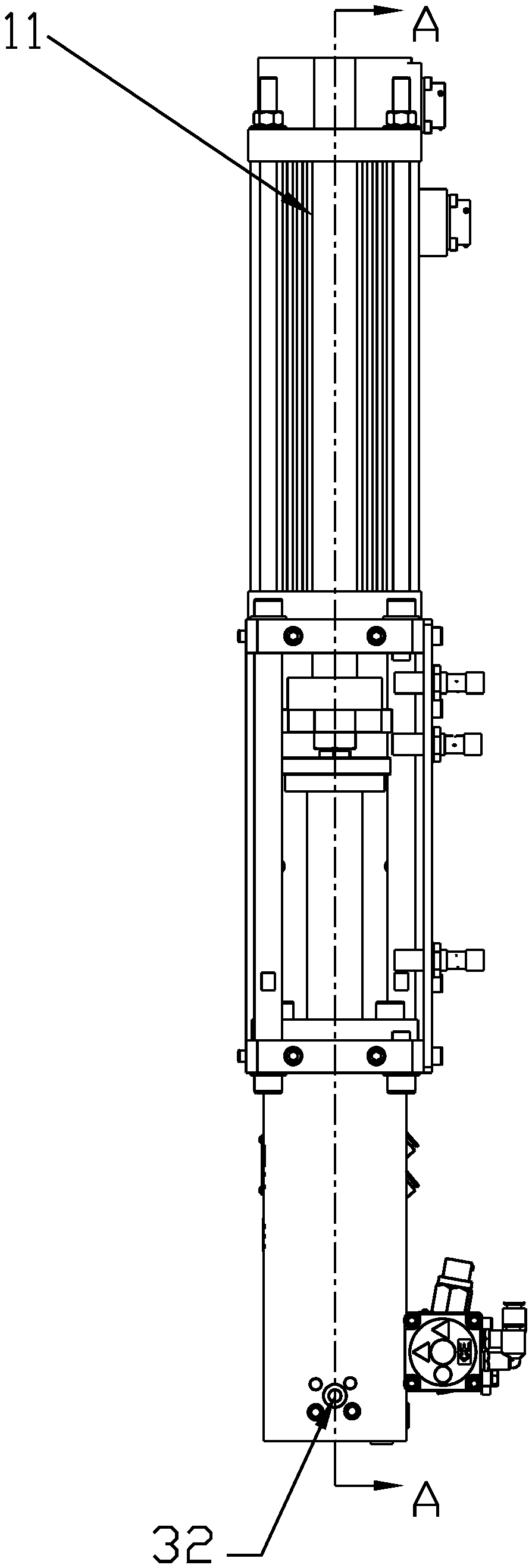
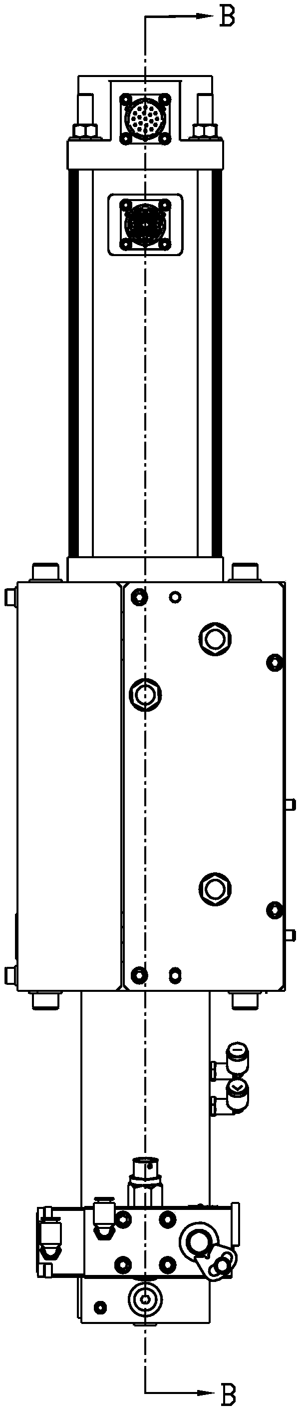
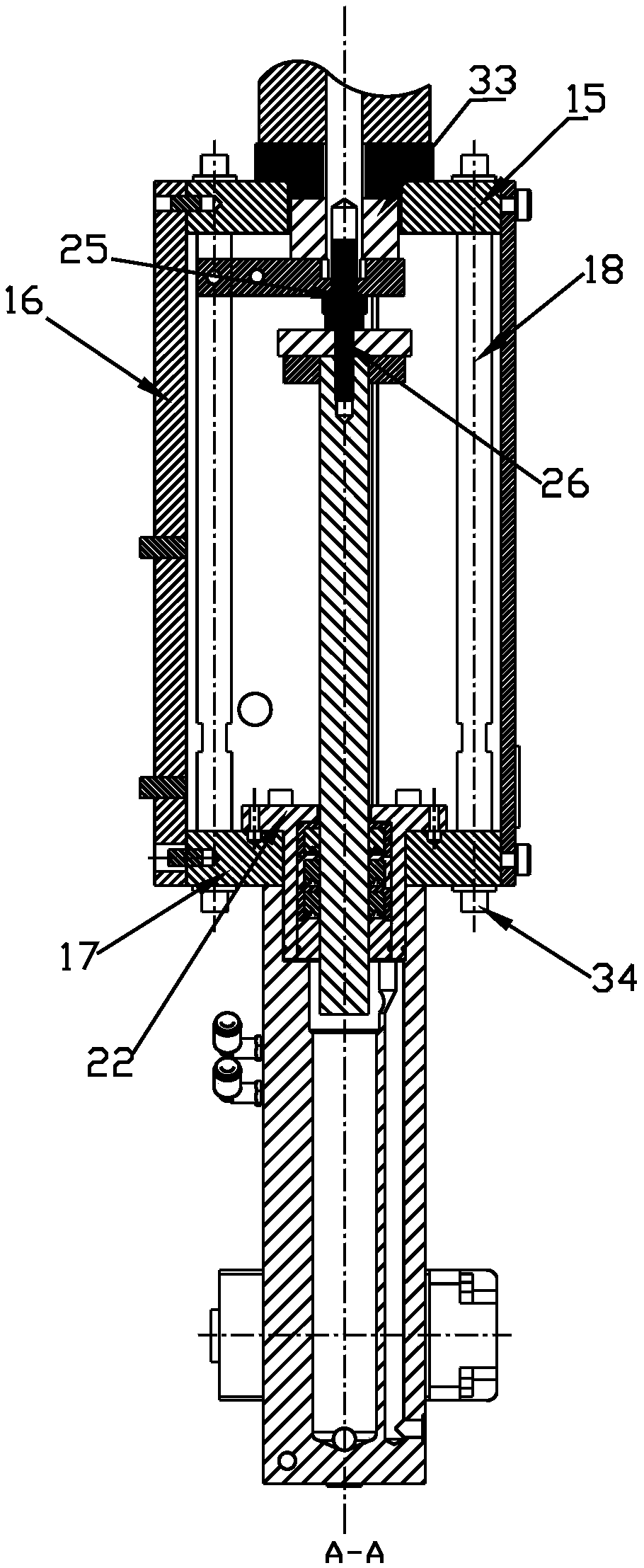
[0022] Such as Figure 1-Figure 4 As shown, a servo glue dosing machine includes a servo electric cylinder 11, a bracket, and a glue cylinder 29. The servo electric cylinder 11 is fixedly connected to the glue cylinder 29 through the bracket. The glue cylinder 29 has a glue inlet chamber with an upper opening. The upper part of the upper seal is equipped with a throat seal metal part 22, the throat seal metal part 22 has a vertical shaft hole, a piston rod 27 is installed in the vertical shaft hole, and a dynamic mechanism for sealing the gap between the piston rod 27 and the vertical shaft hole is installed in the vertical shaft hole. The seal, the diameter of the piston rod 27 is smaller than the inner diameter of the glue inlet chamber, the bottom of the glue cylinder 29 is provided with a glue inlet connected to the glue inlet, and a glue inlet valve 30 is installed in ...


PUM


Abstract

The invention discloses a servo gluing quantification machine. The servo gluing quantification machine comprises a servo electric cylinder, a support and a glue cylinder, wherein the servo electric cylinder is fixedly connected with the glue cylinder through the support; the glue cylinder is provided with a glue feeding cavity with an upper opening; a throat sealing metal piece is mounted at the upper part of the glue feeding cavity in a sealed manner and provided with a vertical shaft hole; a piston rod is mounted in the vertical shaft hole; a dynamic sealing piece for sealing a gap between the piston rod and the vertical shaft hole is mounted in the vertical shaft hole; the diameter of the piston rod is smaller than the inner diameter of the glue feeding cavity; a glue feeding port communicated with the glue feeding cavity is formed in the bottom of the glue cylinder; a glue feeding valve is mounted in the glue feeding port; a push rod of the servo electric cylinder is coaxially arranged above the piston rod; a glue discharging cavity is formed in the glue cylinder, and the upper part of the glue discharging cavity is communicated with the glue feeding cavity through communicating holes; a glue discharging port communicated with the glue discharging cavity is formed in the bottom of the glue cylinder; a glue discharging valve is mounted in the glue discharging port. The servogluing quantification machine has beneficial effects as follows: first-in first-out of glue is guaranteed by adopting an isovolumetric replacement principle, and the problem of glue stacking or glueresidues in the glue cylinder is solved.

Description

technical field [0001] The invention relates to the technical field of gluing devices, in particular to a servo gluing quantitative machine. Background technique [0002] Most of the existing glue dosing mechanisms adopt gear pump metering or servo push cylinder metering mechanism (similar to the structure of syringe injection mode). For the gear pump metering mechanism, the problem is that the metering accuracy is not as high as that of the servo push cylinder, and its accuracy will decrease significantly as time goes on; and for the servo push cylinder metering mechanism currently on the market, the main problems are as follows: 1) Due to Glue is the principle of first-in-last-out, and it is easy to form glue accumulation or residual glue in the glue tank after long-term use; 2) The existing actuator (the actuator integrated with the servo motor, gearbox and ball screw), in In terms of appearance, its disadvantage is that it is bulky and the length of the actuator is too ...

Claims


Application Information

Patent Timeline
Patent Type & Authority Applications(China)
IPC IPC(8): B05C11/10
CPCB05C11/1002
Inventor 张鹏厉建炜
Owner YANTAI KEPAI INTELLIGENT TECH CO LTD
Why Eureka
Try Eureka