Dressing device and dressing method of substrate back grinding member

A technology for back grinding and dressing devices, which is applied in the direction of grinding devices, abrasive surface adjustment devices, grinding/polishing safety devices, etc., and can solve the problems of reduced grinding performance and inability to achieve grinding treatment, etc.

Active Publication Date: 2022-04-01
TOKYO ELECTRON LTD
View PDF8 Cites 0 Cited by
  • Summary
  • Abstract
  • Description
  • Claims
  • Application Information

AI Technical Summary

Problems solved by technology

[0003] However, in the polishing process using such a polishing member, residues (swarf) are generated during polishing. If the residues enter the pores, grooves, etc. of the polishing pad, the polishing performance will be reduced, and sometimes the desired polishing process cannot be achieved.

Method used


Image

  • Dressing device and dressing method of substrate back grinding member
  • Dressing device and dressing method of substrate back grinding member
  • Dressing device and dressing method of substrate back grinding member

Examples


Embodiment Construction

[0059] Below, while referring to the attached Figure 1 Embodiments of the present invention will be described. In addition, in this specification and drawings, the same code|symbol is attached|subjected to the element which has substantially the same functional structure, and repeated description is abbreviate|omitted.

[0060]

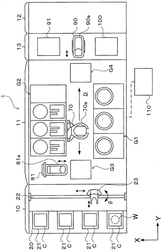
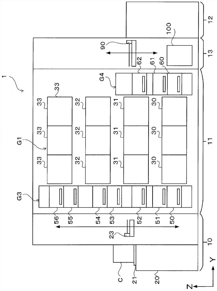
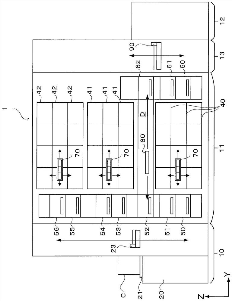
[0061] First, the configuration of a substrate processing system including the trimming device of the present embodiment will be described. figure 1 It is a schematic plan view schematically showing the configuration of the substrate processing system 1 . figure 2 and image 3 It is a front view and a rear view which schematically show the internal structure of the substrate processing system 1, respectively. In the substrate processing system 1 , predetermined processing is performed on a wafer W as a substrate to be processed.

[0062] Substrate processing system 1 such as figure 1 As shown, it has a structure in which the following parts...


PUM


Abstract

The present invention relates to a trimming device and a trimming method for a back grinding member of a substrate. When cleaning and trimming the polishing member for polishing the back surface of the substrate, the cleaning liquid and the residue are not scattered around. The dressing device (200) has a groove member (203) capable of accommodating a polishing pad (131) from above, a top plate portion (201), and a cylindrical shape provided to the lower surface side of the top plate portion (201). skirt (202). The groove member (203) is provided with: a two-fluid nozzle (204), which sprays cleaning liquid and gas to the grinding surface of the polishing pad; a dressing plate (205), which can be in contact with the grinding surface of the polishing pad (131); and a rinsing nozzle (206) that supplies a rinsing liquid to the contact surface between the polishing surface of the polishing pad (131) and the dressing plate (205). Due to the skirt 202, cleaning fluid, grinding wheel chips, or residues are not scattered around.

Description

technical field [0001] The present invention relates to a dressing device and a dressing method of a grinding member on the back surface of a substrate. Background technique [0002] For example, in the manufacturing process of a semiconductor device, the back surface of a semiconductor wafer (in the following description, sometimes simply referred to as a wafer) is polished using a polishing member such as a polishing pad before exposing a pattern, and the substrate is lifted. The flatness of the back, no scratches, dirt, eliminate processing strain. [0003] However, in the polishing process using such a polishing member, residues (swarf) are generated during polishing, and if the residues enter the pores, grooves, etc. of the polishing pad, the polishing performance is reduced, and the desired polishing process may not be achieved. [0004] In view of this problem, in order to maintain the performance of the polishing pad in an appropriate range, the polishing pad is reg...

Claims


Application Information

Patent Timeline
Patent Type & Authority Patents(China)
IPC IPC(8): B24B1/00B24B55/00
CPCB24B1/00B24B55/00B24B27/0084B24B37/105B24B49/12B24B53/007B24B53/095B24B53/14B24B53/017H01L21/67092H01L21/67051H01L21/304H01L21/02052B24B37/042B24B37/205
Inventor 冈本芳树滝口靖史久保明广保坂隼斗小篠龙人
Owner TOKYO ELECTRON LTD
Why Eureka
Try Eureka