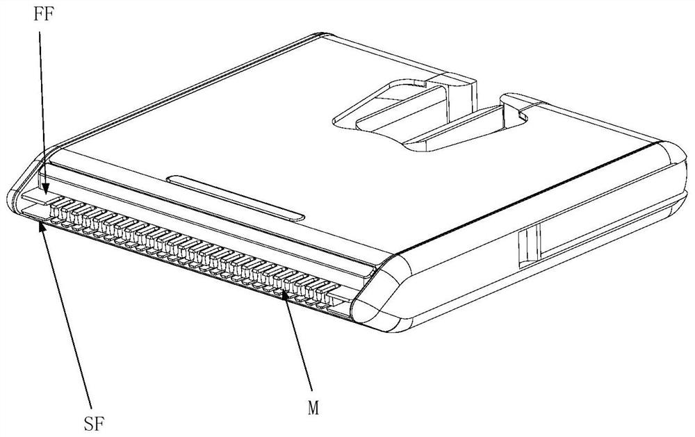
Cutter and hair trimmer with sandwich structure
A sandwich type, tool technology, applied in metal processing and other directions, can solve the problems of user's vulnerability and user's influence, and achieve the effect of prolonging service life, reducing overall weight and reducing the probability of injury
- Summary
- Abstract
- Description
- Claims
- Application Information
AI Technical Summary
Problems solved by technology
Method used
Image
Examples
no. 1 approach
[0060] According to the first embodiment of the present invention, such as image 3 , which shows the movable blade M1 of the knife according to the first embodiment of the present invention; Figure 4 shows as image 3 Enlarged view of part I of the movable blade shown.
[0061] The movable blade M1 of the knife according to the first embodiment of the present invention is integral, and its front end has a row of teeth, and each tooth has a quadrilateral cross-sectional shape, which includes a first pair of sides FPS1 parallel to each other and The first pair of sides FPS1 forms a second pair of sides SPS1 of four acute angles. The first pair of side edges FPS1 is in contact with the two fixed blades, and forms four acute angle cutting edges CE (cutting edges) on the cross section with the two fixed blades, that is, the first cutting edge CE1, the second cutting edge Edge CE2, third cutting edge CE3, and fourth cutting edge CE4. Wherein, each side of the second pair of si...
no. 2 approach
[0063] According to the second embodiment of the present invention, such as Figure 5 , which shows a movable blade M2 of a knife according to a second embodiment of the present invention; Figure 6 shows as Figure 5 Enlarged view of part II of the movable blade shown.
[0064] The movable blade M2 of the knife according to the second embodiment of the present invention is integral, and its front end has a row of teeth, and each tooth has a quadrilateral cross-sectional shape, which includes a first pair of sides FPS2 parallel to each other and The first pair of sides FPS2 forms a second pair of sides SPS2 of four acute angles. The first pair of side edges FPS2 are in contact with the two stationary blades and form four acute shearing edges in cross-section with the two stationary blades. Wherein, each side of the second pair of sides SPS2 has a plurality of arc-shaped recesses, similar to waves, Figure 5 and 6 2 schematically shows a limited number of crests and tr...
no. 3 approach
[0066] According to the third embodiment of the present invention, such as Figure 7 , which shows two stationary blades F3 of a knife according to a third embodiment of the present invention; Figure 8 shows as Figure 7 Side view of part III of the fixed blade F3 shown; Figure 9 is like Figure 7 Enlarged view of section III of the stationary blade F3 shown.
[0067] The two fixed blades of the knife according to the third embodiment of the present invention, that is, the first fixed blade FF3 and the second fixed blade SF3 each have a front end of a row of teeth. Wherein, there is a gap in the middle of the two fixed blades after being assembled into a cutter, which can be used to sandwich the movable blade, and the inner surface of the first fixed blade FF3 and the inner surface of the second fixed blade SF3 are in contact with the movable blade to cut hair . Both sides of the tooth front end of each tooth have rounded corners to prevent the user's skin from being sc...
PUM
 Abstract
Description
Claims
Application Information
 - R&D
- Intellectual Property
- Life Sciences
- Materials
- Tech Scout
- Unparalleled Data Quality
- Higher Quality Content
- 60% Fewer Hallucinations
Browse by: Latest US Patents, China's latest patents, Technical Efficacy Thesaurus, Application Domain, Technology Topic, Popular Technical Reports.
© 2025 PatSnap. All rights reserved.Legal|Privacy policy|Modern Slavery Act Transparency Statement|Sitemap|About US| Contact US: help@patsnap.com


