Fully-automatic energy-saving drip molding method

A fully automatic, plastic-dropping technology, applied in coating and other directions, can solve the problems of low degree of automation and inability to realize mass production of production lines.

Active Publication Date: 2019-02-26
遂宁市金虹机械厂
View PDF8 Cites 4 Cited by
  • Summary
  • Abstract
  • Description
  • Claims
  • Application Information

AI Technical Summary

Problems solved by technology

However, this equipment can only spray plastic on the product, and cannot real

Method used


Image

  • Fully-automatic energy-saving drip molding method
  • Fully-automatic energy-saving drip molding method
  • Fully-automatic energy-saving drip molding method

Examples


Embodiment 1

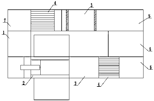
[0092] like Figures 1 to 7 Shown, a kind of fully automatic energy-saving dropping plastic method, comprises the following steps:

[0093]a, Positioning, place the mold on the one-cylinder four-claw system 1, when the sensor XQGY2 senses the mold, the cylinder A12 moves down to the right, pushing the first clip 16, the first clip 16 passes through the telescopic rod A15 and the first The shift fork 14 rotates the first baffle 13 inward, and the two first baffles 13 fix the mold in the right-angle rod 11 to position the mold, then the cylinder A12 moves upward to the left, and the first baffle 13 returns to its original shape and loosens mold;

[0094] b, drop plastic, the mold is pushed into the drop plastic system 2 through the telescopic cylinder, and the telescopic cylinder sends the two molds onto the slide plate, firstly, the first mold 22212 and the second mold 22213 are respectively sent onto the two slide plates 2229, Start the motor A2226 to drive the first screw m...

Embodiment 2

[0122] like Figures 8 to 11 As shown, the transverse screw mandrel 26 is provided with a plastic drop nozzle, an outer cylinder body 221, an inner cylinder body 222 and a spray hole 2211 of the plastic drop nozzle, an inner cylinder body 222 is installed in the outer cylinder body 221, and the The inner cylinder body 222 is provided with a cavity through hole 228, the upper end of the cavity through hole 228 is provided with an air hole cover 223, and the air hole cover 223 is provided with an air flow hole 227, the upper end of the air flow hole 227 is connected with an air pump A229, and the lower end It communicates with the through hole 228 of the cavity. A mechanical seal shaft 2214 is installed in the spray hole 2211. A thimble 224 is movable inside the mechanical seal shaft 2214. The upper end of the thimble 224 is provided with a frustum of a cone 226, and the lower end is provided with a cone. Pointed conical tip 2210, the frustum of a cone 226 is movably arranged be...

Embodiment 3

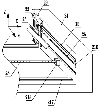
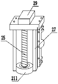
[0132] like Figure 12 As shown, the frame 21 includes a first frame 2221 and a second frame 2222, and a plastic dropping device 2224 and a motor A2226 are installed, and a Bottom plate 2223, on which a slider 2225 and a bearing B2228 are installed, the two ends of the bearing B2228 are respectively installed with one end of a first screw mandrel 2227 and a second screw mandrel 22215, and the other end of the first screw mandrel 2227 One end is installed on the motor A2226 of the first frame 2221, the other end of the second screw mandrel 22215 is installed on the motor A2226 of the second frame 2222, the two ends of the bearing B2228 are provided with the first slide plate 2229, The first sliding plate 2229 is provided with a spiral through hole 22210 and a chute 22211, the first screw 2227 is connected to the first sliding plate 2229 through the spiral through hole 22210, and the second screw 22215 is connected to the second screw through the spiral through hole 22210. Two ...


PUM


Abstract

The invention discloses a fully-automatic energy-saving drip molding method which is characterized by comprising the following steps: positioning, namely placing a mold on a one-cylinder four-claw system; carrying out drip molding, namely pushing the mold into a drip molding system through a telescopic cylinder; heating, namely pushing the mold into a heating system through the telescopic cylinderafter a product is formed on the mold through drip molding; cooling, namely heating the drip molded product on the mold, and pushing the mold into a cooling system through the telescopic cylinder; transferring, namely pushing the cooled mold into a transferring system 5 through the telescopic cylinder; clamping, namely transferring the mold into a clamping system; and demolding, namely pushing the mold into a demolding system through the telescopic cylinder. Through steps of positioning, drip molding, heating, cooling, transferring, clamping and demolding, a spraying molding product is moldedon one production line, fully-automatic production is achieved, and the production efficiency is improved.

Description

technical field [0001] The invention relates to the technical field of mechanical plastic dropping, in particular to a fully automatic energy-saving plastic dropping method. Background technique [0002] Drop plastic is currently one of the few products that still uses manual production for most of the craftsmanship. Its main raw material is to dissolve PVC paste resin in DOP and other fats, and add color paste to form a paste resin mixture of different colors. Drop the paste resin mixture of different colors into the aluminum mold, brass mold, electroforming or silicone mold, and heat it to above 170°C, the PVC paste resin and DOP and other lipids undergo a chemical reaction, and become solid and color Rich, three-dimensional products. [0003] The patent number is CN201720640113.7, and the application date is 2017-06-05. It discloses an NV nozzle for high fluidity material injection molding machine, which includes a nozzle body and a closing needle, and a closing needle ...

Claims


Application Information

Patent Timeline
IPC IPC(8): B29C41/02B29C41/34
CPCB29C41/02B29C41/34
Inventor 魏依光
Owner 遂宁市金虹机械厂
Why Eureka
Try Eureka