
Mounting pylon for aircraft engine, assembly of aircraft, and air craft

A hanger and aircraft technology, applied to the layout/installation of power devices, aircraft parts, power devices on aircraft, etc.

Pending Publication Date: 2019-02-26
AIRBUS SAS
View PDF11 Cites 1 Cited by
  • Summary
  • Abstract
  • Description
  • Claims
  • Application Information

AI Technical Summary

Problems solved by technology

[0008] Although this solution proves to be satisfactory from a structural and safety point of view, it does however have a large overall mass, notably due to the presence of spare lugs and their lateral orientation for fastening to the box The consequences of the device on the panel

Method used


Image

  • Mounting pylon for aircraft engine, assembly of aircraft, and air craft
  • Mounting pylon for aircraft engine, assembly of aircraft, and air craft
  • Mounting pylon for aircraft engine, assembly of aircraft, and air craft

Examples


Embodiment Construction

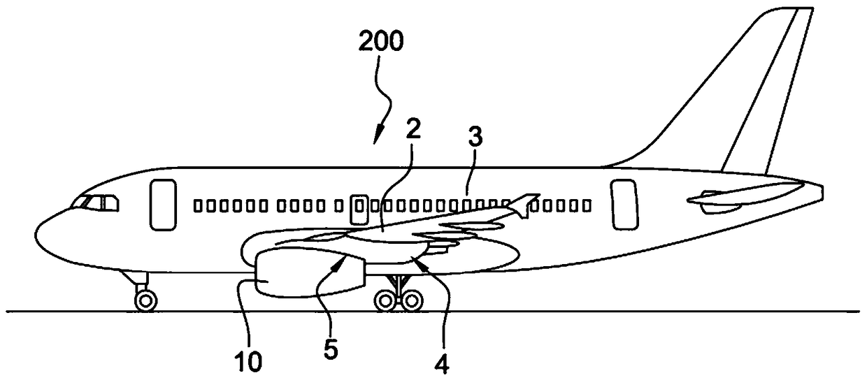
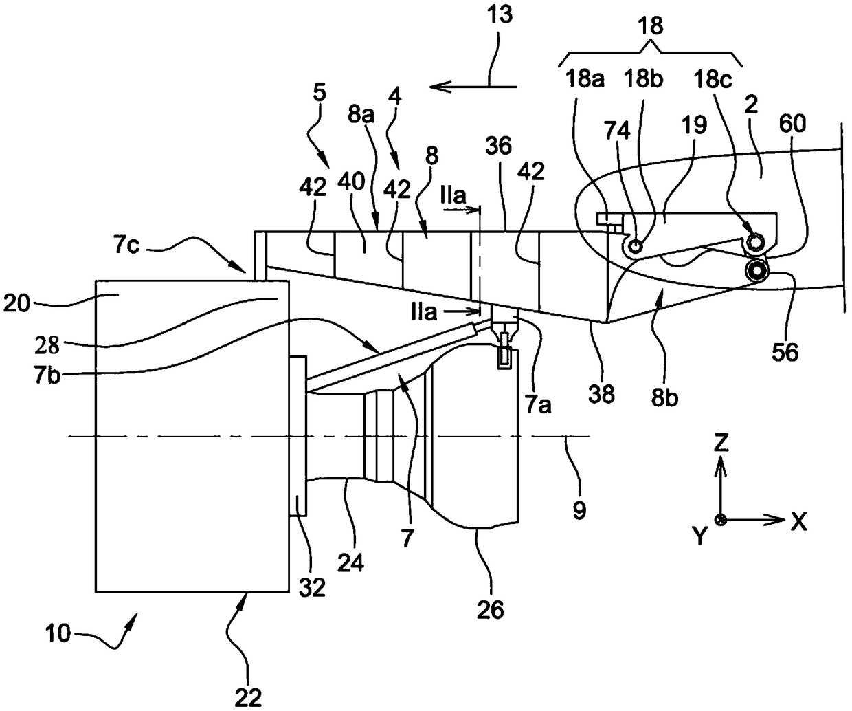
[0045] figure 1 Shown is an aircraft 200 comprising a fuselage 3 to which two wings 2 are fastened ( figure 1 Only one wing is shown). These wings 2 are an integral part with several components 5 that are specific to the invention and will be explained below. Generally, each assembly 5 comprises a wing element (in this case a wing 2 or wing section 2 ), an engine mounting pylon 4 and means for mounting the pylon on the wing. Assembly 5 is intended to carry an engine 10, preferably a twin-flow, twin-shaft engine, such as a jet engine.

[0046] Traditionally, the engine 10 is suspended below the wing 2 . Nevertheless, the invention also covers other solutions in which the engine is located above the wing, or even carried by another wing element, such as a vertical or horizontal tail or a rudder.

[0047] In all the following descriptions, by convention, the X direction corresponds to the longitudinal direction of the pylon 4, which can also be considered similar to the longi...


PUM


Abstract

The invention relates to a mounting pylon for an aircraft engine, an assembly of an aircraft, and an air craft. In order to reduce the mass of a primary structure of a mounting pylon for an engine ofan aircraft, the mounting pylon includes a box and a rear sub-structure fastened to the box which includes two lateral panels, each equipped at its rear end with a first linking portion through whichpasses a first connection orifice that is designed to receive a connection pin of a lateral front wing attachment. The rear sub-structure is made in one piece and includes two opposite lateral flanksthat are respectively fastened to the two lateral panels of the box by fastening elements. Each lateral flank has a second linking portion through which passes a second connection orifice that is aligned with the first connection orifice, and is also designed to receive the connection pin of the lateral front wing attachment.

Description

technical field [0001] The invention relates to the field of assemblies for aircraft, including aircraft engine mounting pylons, wing elements and means for mounting the primary structure of the pylon to the wing elements. [0002] It is preferably suitable for commercial aircraft. Background technique [0003] In existing aircraft, engines such as twin-flow twin-spool jet engines are often mounted under the wings using complex mounting arrangements - also known as EMS (Engine Mounting Structures) or mounting pylons. Such a mounting hanger is known, for example, from document FR3014840. [0004] Commonly used mounting hangers have a main structure, which is also called a rigid structure. This main structure generally has at least one section that is generally box-shaped, that is to say, it is made by joining a lower spar and an upper spar through a plurality of The transverse stiffeners are interlinked. The spars are arranged below and above, while the side panels close ...

Claims


Application Information

Patent Timeline
Patent Type & Authority Applications(China)
IPC IPC(8): B64D27/26B64D27/40
CPCB64D27/402B64D27/404B64D27/40B64C3/32B64D27/18
Inventor 帕斯卡尔·朱勒
Owner AIRBUS SAS
Learn More