Spray nozzle for catalytic cracking experiment and application
A technology for catalytic cracking and testing, applied in the direction of catalytic cracking, cracking, injection devices, etc., can solve the problem that it is impossible to simulate the injection, contact and reaction of various heavy diesel oils, and achieve simple structure, good operating flexibility, and uniform contact Effect
- Summary
- Abstract
- Description
- Claims
- Application Information
AI Technical Summary
Benefits of technology
Problems solved by technology
Method used
Image
Examples
Embodiment 1
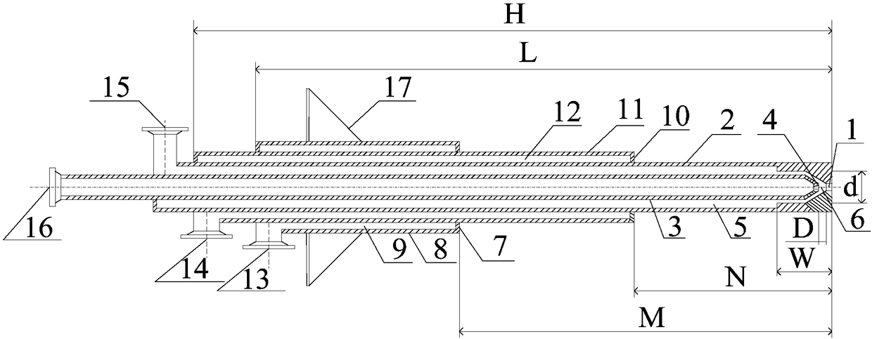
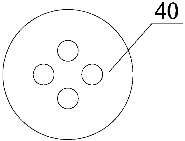
[0070] There are 4 hydrocarbon oil I outer spray holes 40 on the hydrocarbon oil I outer spray head 1 described in Example 1, arranged uniformly on the hydrocarbon oil I outer spray head 1, and the diameter of each spray hole is 1.0mm.
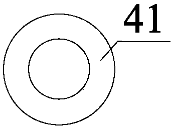
[0071] One hydrocarbon oil I inner spray hole 41 is provided on the hydrocarbon oil I inner spray head 4 described in Example 1, and the diameter of the spray hole on the hydrocarbon oil I inner spray head 4 is 1.1 mm.
[0072] Four hydrocarbon oil II nozzle holes 42 on the hydrocarbon oil II nozzle 7 described in Example 1 are arranged evenly on the hydrocarbon oil II nozzle 7, and the diameter of each nozzle hole is 1.0 mm.
[0073] Four hydrocarbon oil III injection holes 43 on the hydrocarbon oil III nozzle 10 described in Example 1 are arranged evenly on the hydrocarbon oil III nozzle 10, and the diameter of each injection hole is 1.0 mm.
[0074] The distance D between the hydrocarbon oil I inner spray head 4 and the hydrocarbon oil I ou...
Embodiment 2
[0093] There are three hydrocarbon oil I outer spray holes 40 on the hydrocarbon oil I outer spray head 1 described in Example 2, which are evenly arranged on the hydrocarbon oil I outer spray head 1, and the diameter of each spray hole is 1.1 mm.
[0094] One hydrocarbon oil I inner spray hole 41 is provided on the hydrocarbon oil I inner spray head 4 described in Example 2, and the diameter of the spray hole on the hydrocarbon oil I inner spray head 4 is 1.2 mm.
[0095] Four hydrocarbon oil II injection holes 42 on the hydrocarbon oil II nozzle 7 described in Example 2 are arranged uniformly on the hydrocarbon oil II nozzle 7, and the diameter of each injection hole is 1.1 mm.
[0096] Four hydrocarbon oil III injection holes 43 on the hydrocarbon oil III nozzle 10 described in Example 2 are arranged uniformly on the hydrocarbon oil III nozzle 10 , and the diameter of each injection hole is 1.1 mm.
[0097] The distance D between the hydrocarbon oil I inner spray head 4 and...
Embodiment 3
[0116] One hydrocarbon oil I outer spray hole 40 is provided on the hydrocarbon oil I outer spray head 1 described in Example 3, and the diameter of the spray hole on the hydrocarbon oil I outer spray head 1 is 2 mm.
[0117] One hydrocarbon oil I inner spray hole 41 is provided on the hydrocarbon oil I inner spray head 4 described in Example 3, and the diameter of the spray hole on the hydrocarbon oil I inner spray head 4 is 1.3 mm.
[0118] Six hydrocarbon oil II injection holes 42 on the hydrocarbon oil II nozzle 7 described in Example 3 are arranged evenly on the hydrocarbon oil II nozzle 7, and the diameter of each injection hole is 0.9 mm.
[0119] Six hydrocarbon oil III injection holes 43 are provided on the hydrocarbon oil III nozzle 10 described in Example 3, arranged uniformly on the hydrocarbon oil III nozzle 10, and each injection hole has a diameter of 0.9 mm.
[0120] The distance D between the hydrocarbon oil I inner spray head 4 and the hydrocarbon oil I outer...
PUM
 Abstract
Description
Claims
Application Information
 - R&D
- Intellectual Property
- Life Sciences
- Materials
- Tech Scout
- Unparalleled Data Quality
- Higher Quality Content
- 60% Fewer Hallucinations
Browse by: Latest US Patents, China's latest patents, Technical Efficacy Thesaurus, Application Domain, Technology Topic, Popular Technical Reports.
© 2025 PatSnap. All rights reserved.Legal|Privacy policy|Modern Slavery Act Transparency Statement|Sitemap|About US| Contact US: help@patsnap.com


