Novel steel plate pile even wall

A technology of steel sheet pile and ground connection wall, which is applied in sheet pile wall, construction, infrastructure engineering, etc., can solve the problems of poor bonding strength and sealing, limited weight of steel sheet pile, low flexibility of use, etc. Improves structural strength and prevents tilting

Active Publication Date: 2019-02-26
FOSHAN UNIVERSITY
View PDF6 Cites 0 Cited by
  • Summary
  • Abstract
  • Description
  • Claims
  • Application Information

AI Technical Summary

Problems solved by technology

[0003] Existing steel sheet piles are usually a piece of flat section steel, and its connection structures are generally arranged on the left and right sides. When used, they can only be connected in a straight line. In non-linear areas and right-angle turns, it is difficult to completely connect, and the bonding strength and sealing performance are relatively poor. In addition, the steel sheet pile needs to be buried in the soil when it is used. The weight of the steel sheet pile is limited and the center of gravity cannot be changed. The resistance is relatively large when buried. At the same time, the general steel sheet pile can only be buried by external pile drivers and other auxiliary devices, which is flexible lower sex
[0004] A new type of steel sheet pile is disclosed in CN207452881U, a Chinese utility model patent application publication. Although the new type of steel sheet pile is equipped with a cylindrical main steel sheet pile assembly, it has good cross-sectional properties and bending resistance, and it is different from the linear auxiliary steel sheet pile. The combination improves the bending resistance and impact resistance of the formed steel sheet pile wall. However, the new steel sheet pile still only has a pair of symmetrically arranged connecting components, which has the disadvantage of being difficult to connect completely with non-linear areas and right-angle turns.

Method used


Image

  • Novel steel plate pile even wall
  • Novel steel plate pile even wall
  • Novel steel plate pile even wall

Examples


Embodiment Construction

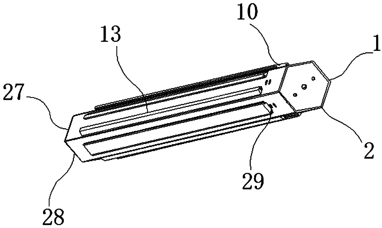
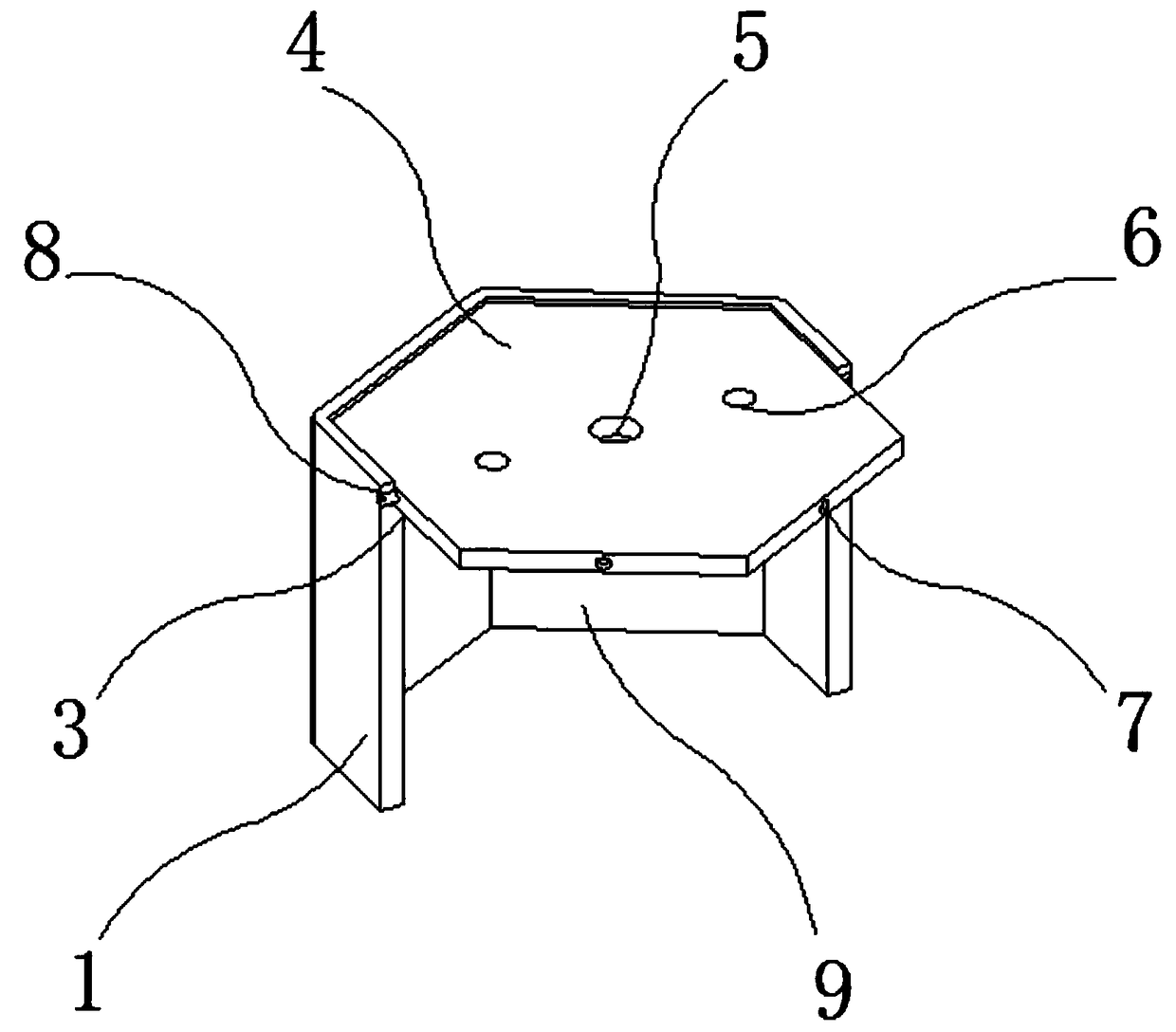
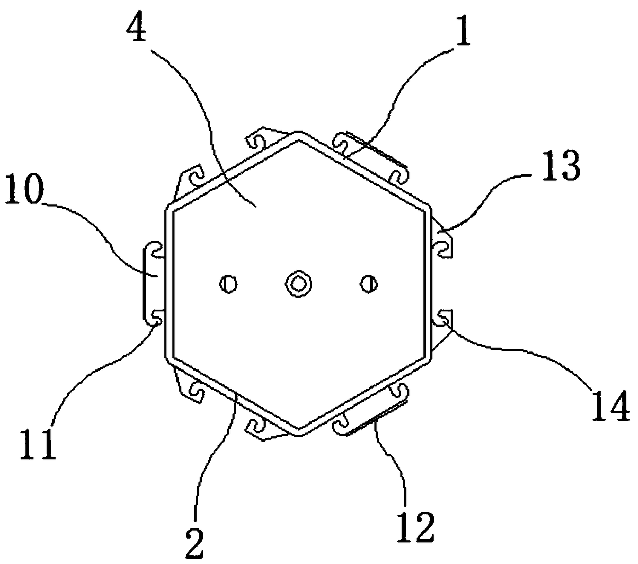
[0031] The technical solutions in the embodiments of the present invention will be clearly and completely described below in conjunction with the accompanying drawings in the embodiments of the present invention. Obviously, the described embodiments are only a part of the embodiments of the present invention, rather than all the embodiments.

[0032] In the description of the present invention, unless otherwise specified, "plurality" means two or more; the terms "upper", "lower", "left", "right", "inner", "outer" , "Front", "Back", "Head", "Tail", etc. indicate the orientation or positional relationship based on the orientation or positional relationship shown in the drawings, and are only for the convenience of describing the present invention and simplifying the description, not It indicates or implies that the pointed device or element must have a specific orientation, be constructed and operated in a specific orientation, and therefore cannot be understood as a limitation of t...


PUM


Abstract

The invention discloses a novel steel plate pile even wall and relates to the technical field of building engineering devices, in particular to a pile body and a fixing rack. An operation opening is formed in the top of the pile body, a bayonet groove is formed in the inner side of the operation opening, and a cover plate is installed in the middle of the bayonet groove; the cover plate is embedded in the bayonet groove, a rope penetration hole is formed in the upper surface of the cover plate, and vent holes are formed in the left and right sides of the rope penetration hole; a connection hole is formed in the lower portion of the operation opening, a fixing hole is formed in the outer side of the fixing rack, and the fixing rack is located at the outer side of the connection hole. According to the novel steel plate pile even wall, through a sealing structure formed by the cover plate and the bayonet groove, the operation opening of the top of the pile body is sealed, the cover plateis embedded in the bayonet groove, and the situation can be prevented that soil or other impurities fall in a center cylinder of the inner side of the pile body; through normal application of an interference device, the wall is damaged, and the reliability and safety of the wall are conveniently improved.

Description

Technical field [0001] The invention relates to the technical field of construction engineering devices, in particular to a new type of steel sheet pile ground connecting wall. Background technique [0002] The steel sheet pile is a kind of steel structure with a linkage device on the edge, and this linkage device can be freely combined to form a continuous and compact steel structure with a retaining wall or a water retaining wall. The general steel sheet pile is a type of steel with a lock , Its cross-sections are straight, trough, Z-shaped, etc., and there are various sizes and interlocking forms. The common ones are Larsen, Lacvanner, etc. The steel sheet pile has high strength and is easy to drive into hard soil. It can be constructed in deep water. If necessary, diagonal support is added to form a cage. It has good waterproof performance and can be formed into cofferdams of various shapes as required and can be reused many times. Therefore, it has a wide range of uses. [00...

Claims


Application Information

Patent Timeline
Patent Type & Authority Applications(China)
IPC IPC(8): E02D5/04E02D5/08
CPCE02D5/04E02D5/08E02D2300/0029E02D2600/20
Inventor 雷元新邓坚黄雅攀徐佳兴
Owner FOSHAN UNIVERSITY
Why Eureka
Try Eureka