Cooperative multi-channel and opportunistic routing method applied to wireless network

A wireless network, multi-channel technology, applied in the field of collaborative multi-channel and opportunistic routing, which can solve problems such as limited revenue

Active Publication Date: 2019-02-26
UNIV OF ELECTRONIC SCI & TECH OF CHINA
5 Cites 0 Cited by

AI-Extracted Technical Summary

Problems solved by technology

[0005] The present invention provides a method for cooperative multi-channel and opportunistic routing applied in a wireless network, which solves the technical problem of limited income in the exis...

Abstract

The invention discloses a cooperative multi-channel and opportunistic routing method applied to a wireless network. The method includes the following steps: evaluating the quality of all available channels through a sender, channel ranking information pa is sent out through an anycasting mode, calculating the benefit/cost ratio of channel communication after a receiver receives the channel rankingto select a channel and a sender with which the channel cooperates, taking a vote to select other senders that are not selected, calculating the additional expected transmission times cETX by the sender to select an appropriate channel. The transmission efficiency and conflict situations are considered comprehensively by using a three-party agreement method. The test results show that the methodcan greatly improve the transmission performance of a wireless network.

Application Domain

Wireless communication

Technology Topic

Transmission performanceThree party +6

Image

  • Cooperative multi-channel and opportunistic routing method applied to wireless network
  • Cooperative multi-channel and opportunistic routing method applied to wireless network
  • Cooperative multi-channel and opportunistic routing method applied to wireless network

Examples

  • Experimental program(1)

Example Embodiment

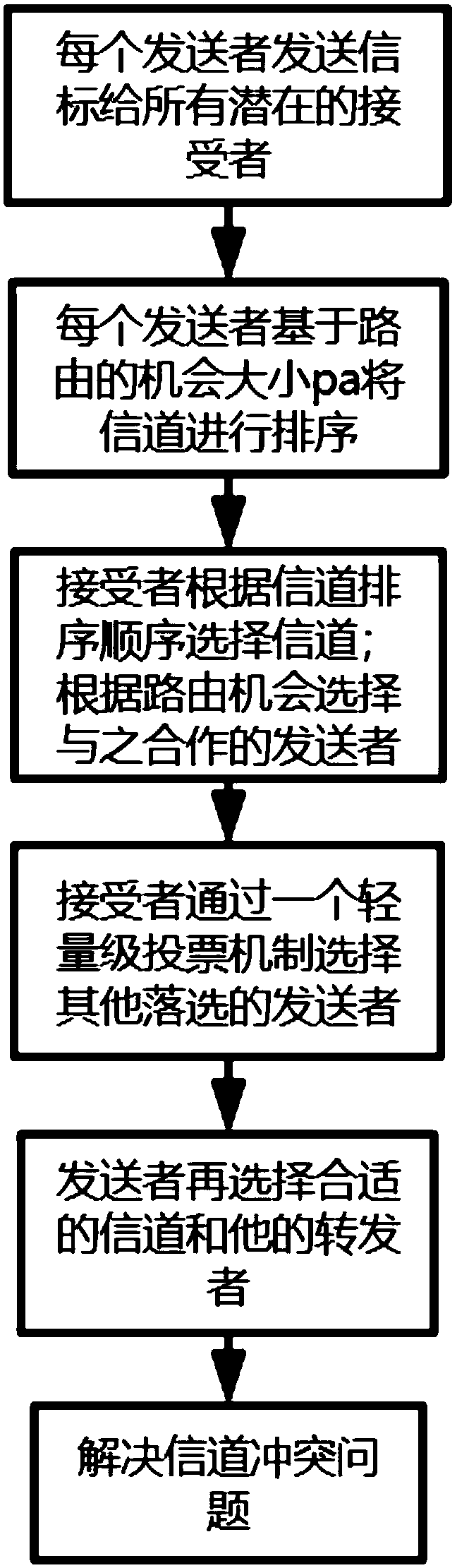
[0039] The present invention provides a method for cooperative multi-channel and opportunistic routing applied in wireless networks. The method considers the transmission efficiency of the sender and the conflict of the receiver at the same time, and combines the characteristics of both multi-channel communication and opportunistic routing. At the same time, their advantages are retained and the effectiveness of low-power wireless network transmission is improved.
[0040] In order to be able to understand the above objectives, features and advantages of the present invention more clearly, the present invention will be further described in detail below in conjunction with the accompanying drawings and specific embodiments. It should be noted that the embodiments of the present application and the features in the embodiments can be combined with each other if they do not conflict with each other.
[0041] In the following description, many specific details are explained in order to fully understand the present invention. However, the present invention can also be implemented in other ways different from the scope described here. Therefore, the protection scope of the present invention is not disclosed below. Limitations of specific embodiments.
[0042] Please refer to figure 1 This application provides the main steps of the method of allocating channels of the present invention: each sender sends a beacon to all potential recipients, receives the bitmap returned from the recipient, and puts "1" to indicate the receipt of the data packet , "0" means the loss of the data packet; the sender uses the channel-based routing opportunity method to sort all possible channels according to the bitmap in step 1, and sends them out; each receiver receives the channel sort order Then, by calculating the benefit/cost ratio ρ i To select the sender to cooperate with, and at the same time select the channel ranked first as the working channel; the recipient adopts a lightweight voting mechanism to select the remaining unselected senders and channels; the recipient completes After the selection of the channel and the sender, the sender determines the channel and repeater to be used by calculating the size of the additional expected number of transmissions cETX; if the channel selected by the sender and the receiver are inconsistent, the receiver will base on the sender’s Channel selection to change its main channel. among them,
[0043] A. The sender sends beacons to all potential receivers and receives the returned information:
[0044] 1) We convert the reception and loss of packets in the link into bitmaps, with "1" indicating the receipt of data packets, and "0" indicating the loss of data packets.
[0045] B. The sender sorts all possible channels according to the returned information, and sends the sorting result in the form of anycast:
[0046] 1) The average routing opportunity is used as the routing opportunity of a sender. The calculation formula of the average routing opportunity is:
[0047]
[0048] Where p a Represents the packet reception rate of anycast, among them, Represents the bitwise XOR operation, |b| represents the number of "1"s in the bitmap b, and m represents the length of the bitmap of the bitmap set Bs of the sender s. From this we can calculate the average routing opportunity size on each channel.
[0049] 2) After the sender sorts all the channel conditions, the sorted information is sent to all possible receivers so that the receiver can select the appropriate channel and sender.
[0050] C. After receiving the channel ranking information from all potential senders, each receiver decides to choose a working channel and a sender with whom it wants to cooperate. Specifically, the receiver decides which channel to choose and the cooperating sender by calculating a benefit/cost ratio:
[0051] ρ i = P a (i,j)/n c (i)
[0052] Where p a (i,j) represents the opportunity size of routing on channel i calculated by sender j, n c (i) represents the number of senders on channel i. In this way, the sender and channel with the largest ρ will be selected as the working channel and sender.
[0053] D. After the receiver has selected the main channel and the corresponding sender, there are other unselected senders. Here, a lightweight voting mechanism is adopted: for each channel, we record their ranking information in different senders And check which channel is most likely to be selected. If a channel is more likely to be selected in a lower channel ranking, then we will choose this channel first and choose the highest ranked sender.
[0054] E. After the receiver has completed the selection of the channel and the corresponding sender, and has voted for other senders and channels that are not the first choice, it is the sender's turn to decide which channel to work on. Here, we comprehensively consider the possibility of minimizing the expected number of transmissions ETX and the channel conflict, and select the channel by calculating the additional expected number of transmissions cETX:
[0055] cETX=ETX×(1+q collision )
[0056] Where q collision Is the probability of collision, the calculation formula is:
[0057] q collision = 1-p st -p nt
[0058] p st Indicates the probability of a successful transmission, p nt Indicates that there is no possibility that the sender will try to transmit. The calculation formula is as follows:
[0059]
[0060] N is the number of outbound links, p ta Is the transmission attempt probability. p ta The calculation formula is:
[0061]
[0062] Where T trans Represents the backoff timer for data transmission.
[0063] In this way, we can calculate the additional expected number of transmissions, allowing the sender to select the appropriate channel for work.
[0064] F. If the channels selected by the sender and the receiver are different, we propose a refined correction method: the receiver changes its main channel according to the channel selected by the sender. Since the channels of all senders have been determined at this time, the receiver has to change the channel: 1. The channel is included in the sender's bitmap, 2. The link quality from the sender is better than that of other senders.
[0065] Although the preferred embodiments of the present invention have been described, those skilled in the art can make additional changes and modifications to these embodiments once they learn the basic creative concept. Therefore, the appended claims are intended to be interpreted as including the preferred embodiments and all changes and modifications falling within the scope of the present invention.
[0066] Obviously, those skilled in the art can make various changes and modifications to the present invention without departing from the spirit and scope of the present invention. In this way, if these modifications and variations of the present invention fall within the scope of the claims of the present invention and their equivalent technologies, the present invention is also intended to include these modifications and variations.

PUM

no PUM

Description & Claims & Application Information

We can also present the details of the Description, Claims and Application information to help users get a comprehensive understanding of the technical details of the patent, such as background art, summary of invention, brief description of drawings, description of embodiments, and other original content. On the other hand, users can also determine the specific scope of protection of the technology through the list of claims; as well as understand the changes in the life cycle of the technology with the presentation of the patent timeline. Login to view more.
Why Eureka
Try Eureka