Rotary lifting type assembly and application thereof
A technology of rotating lifting and components, which is applied in the field of household appliances, can solve problems such as inconvenient use and complex structure, and achieve the effect of simple cost, simple structure and simplified structure
- Summary
- Abstract
- Description
- Claims
- Application Information
AI Technical Summary
Problems solved by technology
Method used
Image

Examples
Embodiment 1
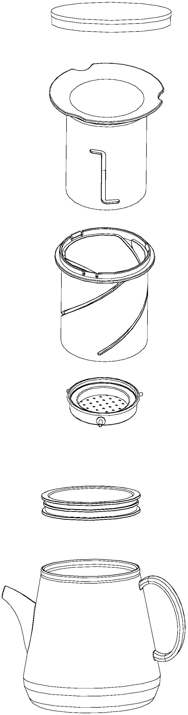
[0100] a teapot such as Figure 4 As shown, it includes a pot body 1000 and the above-mentioned rotary lifting assembly, which includes: an outer sleeve 2100 , an inner sleeve 2200 and a tray 2300 ; the teapot also includes a fixing member 3000 and a cover 4000 .
[0101] The outer sleeve 2100 has a cylindrical side wall 2110, and the outer sleeve 2100 is provided with a spiral external thread groove 2120, and the top view projection of the external thread groove 2120 is arc-shaped.
[0102] The inner sleeve 2200 is sleeved in the outer sleeve 2100 and can rotate coaxially with the outer sleeve 2100. The inner sleeve 2200 is provided with a spiral internal thread groove 2210, the The top view projection of the internal thread groove 2210 is arc-shaped, and the thread direction of the external thread groove 2120 is opposite to the thread direction of the internal thread groove 2210 .
[0103] The tray part 2300 includes a tray part 2310 and a connection part 2320, the tray par...
Embodiment 2
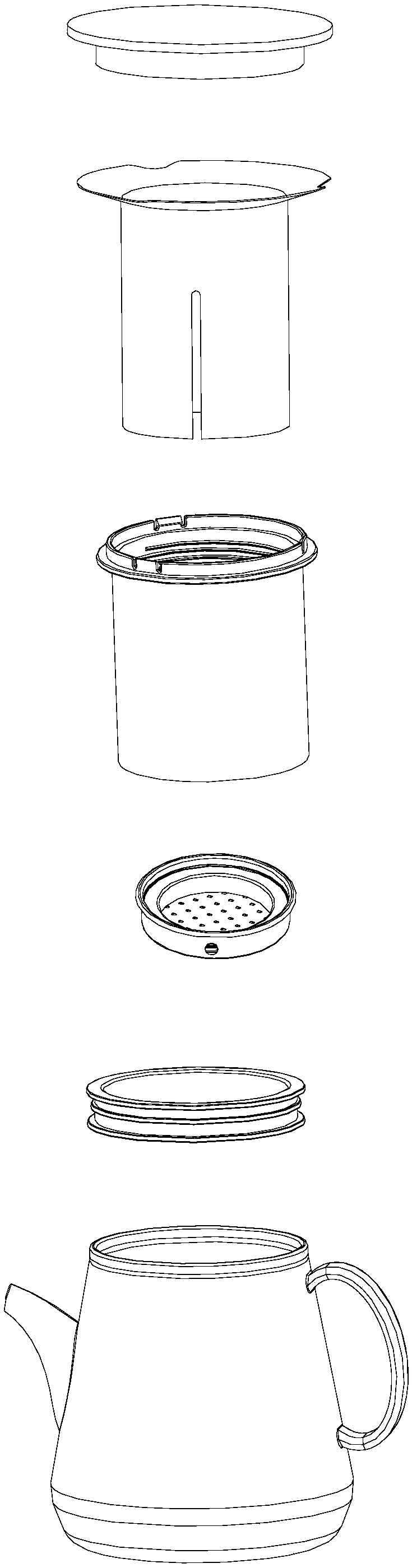
[0115] a teapot such as Image 6 As shown, it includes a pot body 1000 and the above-mentioned rotary lifting assembly, and the rotary lifting assembly includes: an outer sleeve 2100, an inner sleeve 2200 and a tray member 2300; the teapot also includes a fixing member 3000, a cover 4000 and a knob 5000.
[0116] The outer sleeve 2100 has a cylindrical side wall 2110, on which is provided a spiral external thread groove 2120, and the top view projection of the external thread groove 2120 is arc-shaped.
[0117] The inner sleeve 2200 is sleeved in the outer sleeve 2100 and can rotate coaxially with the outer sleeve 2100. The inner sleeve 2200 is provided with a spiral internal thread groove 2210, the The top view projection of the internal thread groove 2210 is arc-shaped, and the thread direction of the external thread groove 2120 is opposite to the thread direction of the internal thread groove 2210 .
[0118] The tray part 2300 includes a tray part 2310 and a connection pa...
Embodiment 3
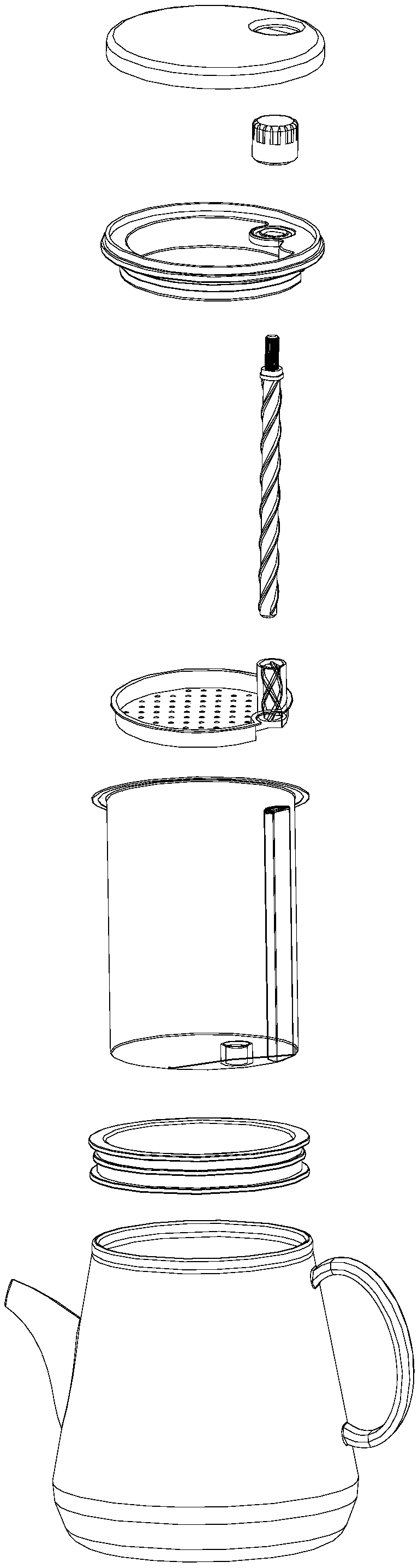
[0128] a teapot such as Figure 7 As shown, it includes a pot body 1000 and the above-mentioned rotary lifting assembly, and the rotary lifting assembly includes: an outer sleeve 2100, an inner sleeve 2200 and a tray member 2300; the teapot also includes a fixing member 3000, a cover 4000 and a knob 5000.
[0129] The outer sleeve 2100 has a cylindrical side wall 2110, and the outer sleeve 2100 is provided with a spiral external thread groove 2120, and the top view projection of the external thread groove 2120 is arc-shaped.
[0130] The inner sleeve 2200 is sleeved in the outer sleeve 2100 and can rotate coaxially with the outer sleeve 2100. The inner sleeve 2200 is provided with a spiral internal thread groove 2210, the The top view projection of the internal thread groove 2210 is arc-shaped, and the thread direction of the external thread groove 2120 is opposite to the thread direction of the internal thread groove 2210 .
[0131] The tray part 2300 includes a tray part 2...
PUM
 Abstract
Description
Claims
Application Information
 - Generate Ideas
- Intellectual Property
- Life Sciences
- Materials
- Tech Scout
- Unparalleled Data Quality
- Higher Quality Content
- 60% Fewer Hallucinations
Browse by: Latest US Patents, China's latest patents, Technical Efficacy Thesaurus, Application Domain, Technology Topic, Popular Technical Reports.
© 2025 PatSnap. All rights reserved.Legal|Privacy policy|Modern Slavery Act Transparency Statement|Sitemap|About US| Contact US: help@patsnap.com