Conveying device for high-viscosity material low in flowing property and application method

A technology of flow performance and conveying device, applied in the direction of injection device, liquid injection device, etc., can solve the problems of high viscosity, high solid material conveying difficulty, high viscosity material poor fluidity, difficult to replenish materials in time, etc., to reduce gas. The effect of acupuncture phenomenon, accurate temperature measurement, and avoiding frequent alarms

Active Publication Date: 2019-03-01
上海船舶工艺研究所(中国船舶集团有限公司第十一研究所)
View PDF9 Cites 2 Cited by
  • Summary
  • Abstract
  • Description
  • Claims
  • Application Information

AI Technical Summary

Problems solved by technology

[0002] At present, in the manufacturing process of steel structures such as ships and ocean engineering, the surface of steel plates needs to be sprayed with anti-corrosion coatings, especially in heavy-duty anti-corrosion areas such as ballast tanks, it is necessary to use high-solid two-component paints and coatings. Viscous materials have poor fluidity, especially at low temperatures, and the flow performance is even worse
[0003] In the process of conveying high-solid viscous materials, it is difficult for the materials to replenish and flow in time to generate gaps, which brings difficulties to the transportation of high-viscosity and high-solid materials.

Method used


Image

  • Conveying device for high-viscosity material low in flowing property and application method
  • Conveying device for high-viscosity material low in flowing property and application method
  • Conveying device for high-viscosity material low in flowing property and application method

Examples


Embodiment Construction

[0023] The specific embodiments of the present invention will be described in detail below in conjunction with the accompanying drawings, so that those skilled in the art can more clearly understand how to practice the present invention. While the invention has been described in connection with preferred specific embodiments thereof, these embodiments are illustrative only and are not intended to limit the scope of the invention.

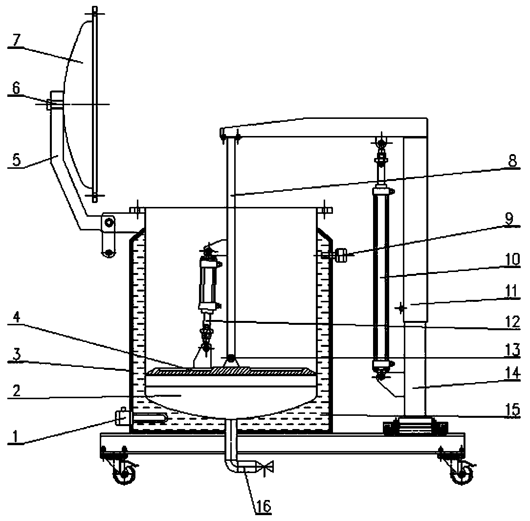
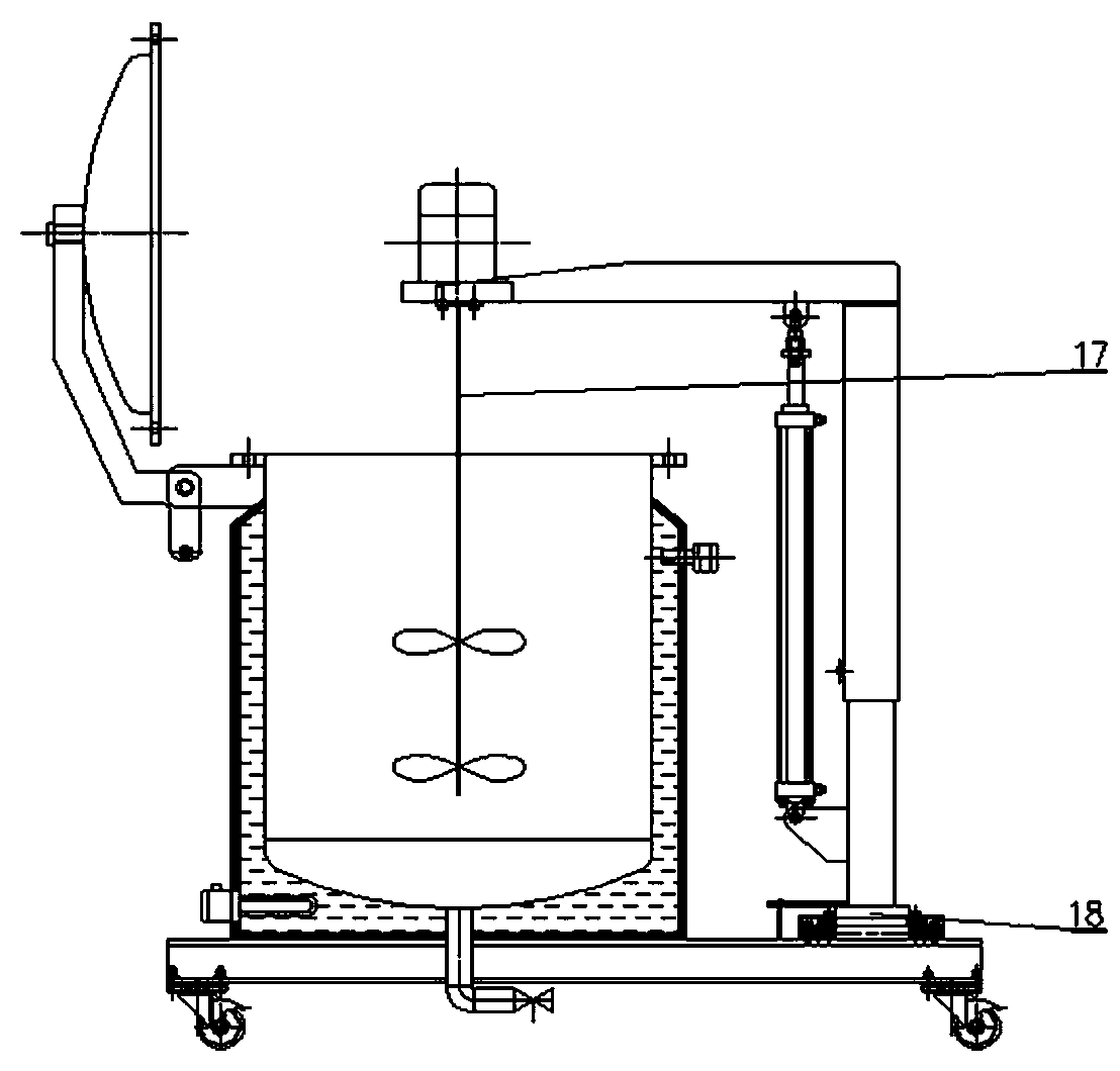
[0024] Such as figure 1 As shown, a conveying device for highly viscous materials with low fluidity is different from the prior art in that the conveying device includes a material storage container and a movable upper cover matched therewith, and one side of the material storage container A lifting device is provided, the lifting device includes a rotatable beam, the beam includes a disc-shaped tooling support, and a stirring module and a feeding module are arranged under the tooling support.

[0025] Preferably, the size of the mixing module and ...


PUM


Abstract

The invention discloses a conveying device for a high-viscosity material low in flowing property. The conveying device comprises a material storage container and a movable upper cover, wherein the movable upper cover is matched with the material storage container. A lifting device is arranged at one side of the material storage container and comprises a rotatable cross beam. The cross beam comprises a disc-shaped tool support. A stirring module and a material supply module are arranged below the tool support. The material supply module comprises a piston rod and a piston, wherein the piston isconnected with the piston rod. An overturning hydraulic cylinder is arranged between the piston rod and the piston. A heat preservation layer is arranged outside the material storage container. The portion between the heat preservation layer and the material storage container is filled with heat conduction oil. An anti-explosion heating device is arranged on the lower portion of the heat preservation layer and used for heating the heat conduction oil in the heat preservation layer. By means of the stirring module and the material supply module which can be switched, materials can be conveyedefficiency, conveniently and rapidly; air pockets are prevented from being generated; and meanwhile, the material storage container has the heating function, and the material flowability is further improved.

Description

technical field [0001] The present invention mainly relates to the technical field of conveying devices, in particular to a conveying device for high-viscosity materials with low fluidity and a method for using them, especially for high viscosity, low Conveyor for liquid materials. Background technique [0002] At present, in the manufacturing process of steel structures such as ships and ocean engineering, the surface of steel plates needs to be sprayed with anti-corrosion coatings, especially in heavy-duty anti-corrosion areas such as ballast tanks, it is necessary to use high-solid two-component paints and coatings. Viscous materials have poor fluidity, especially when the temperature is low, the fluidity is even worse. [0003] In the process of conveying high-solid viscous materials, it is difficult for the materials to replenish and flow in time to generate gaps, which brings difficulties to the transportation of high-viscosity and high-solid materials. [0004] Ther...

Claims


Application Information

Patent Timeline
Patent Type & Authority Applications(China)
IPC IPC(8): B05B9/047B05B15/25B05B9/00
CPCB05B9/002B05B9/047B05B15/25
Inventor 刘洪伟姜星星缪逢吉
Owner 上海船舶工艺研究所(中国船舶集团有限公司第十一研究所)
Why Eureka
Try Eureka