Automobile front bumper spraying hanging tool
A technology for front bumpers and automobiles, which is applied in the direction of injection devices, etc., can solve the problems of low production efficiency, insufficient hanging reliability, and inability to spray the front bumper at the same time, and achieves the effect of improving production efficiency and reducing waste.
- Summary
- Abstract
- Description
- Claims
- Application Information
AI Technical Summary
Problems solved by technology
Method used
Image

Examples
Embodiment 1
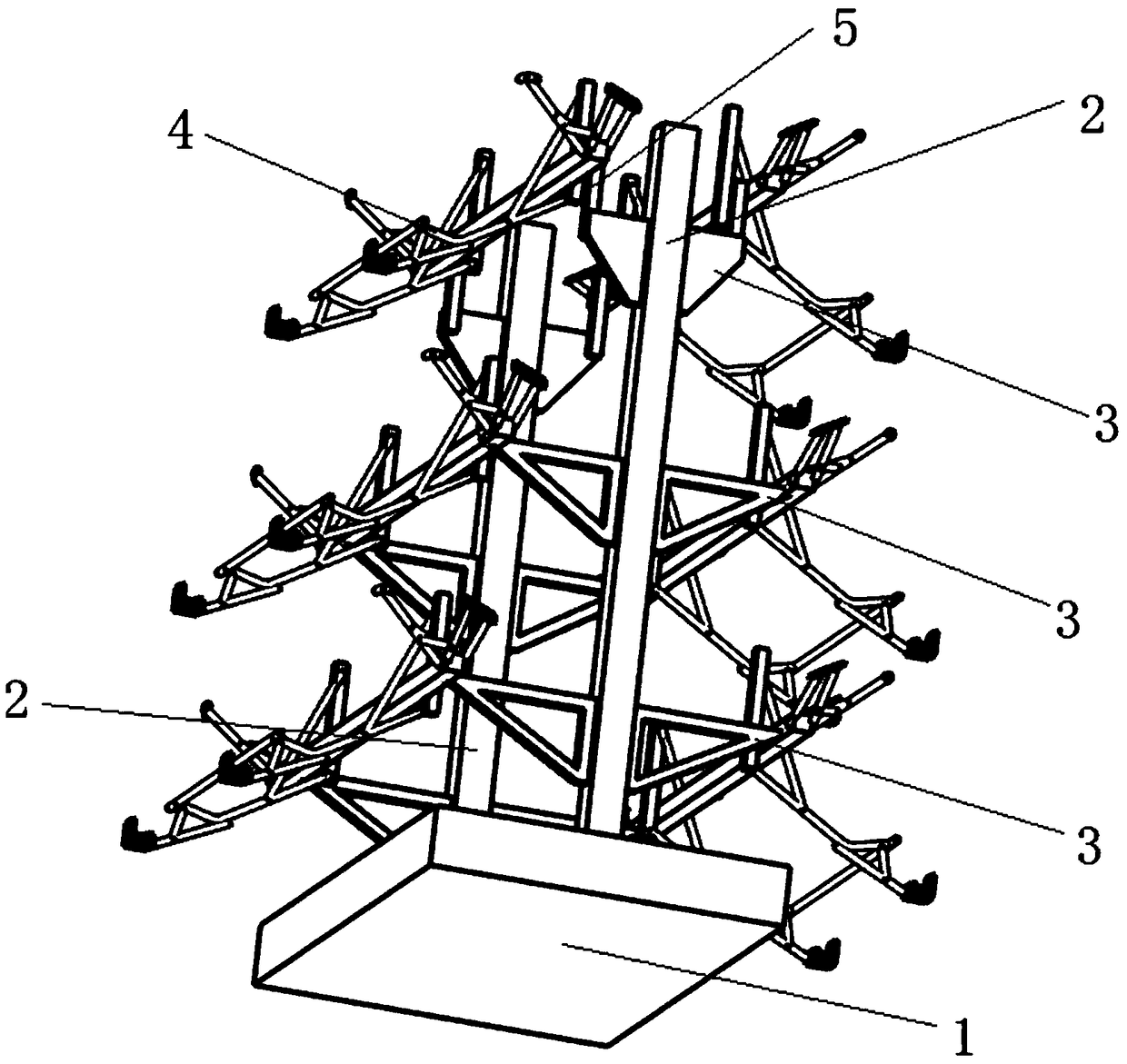
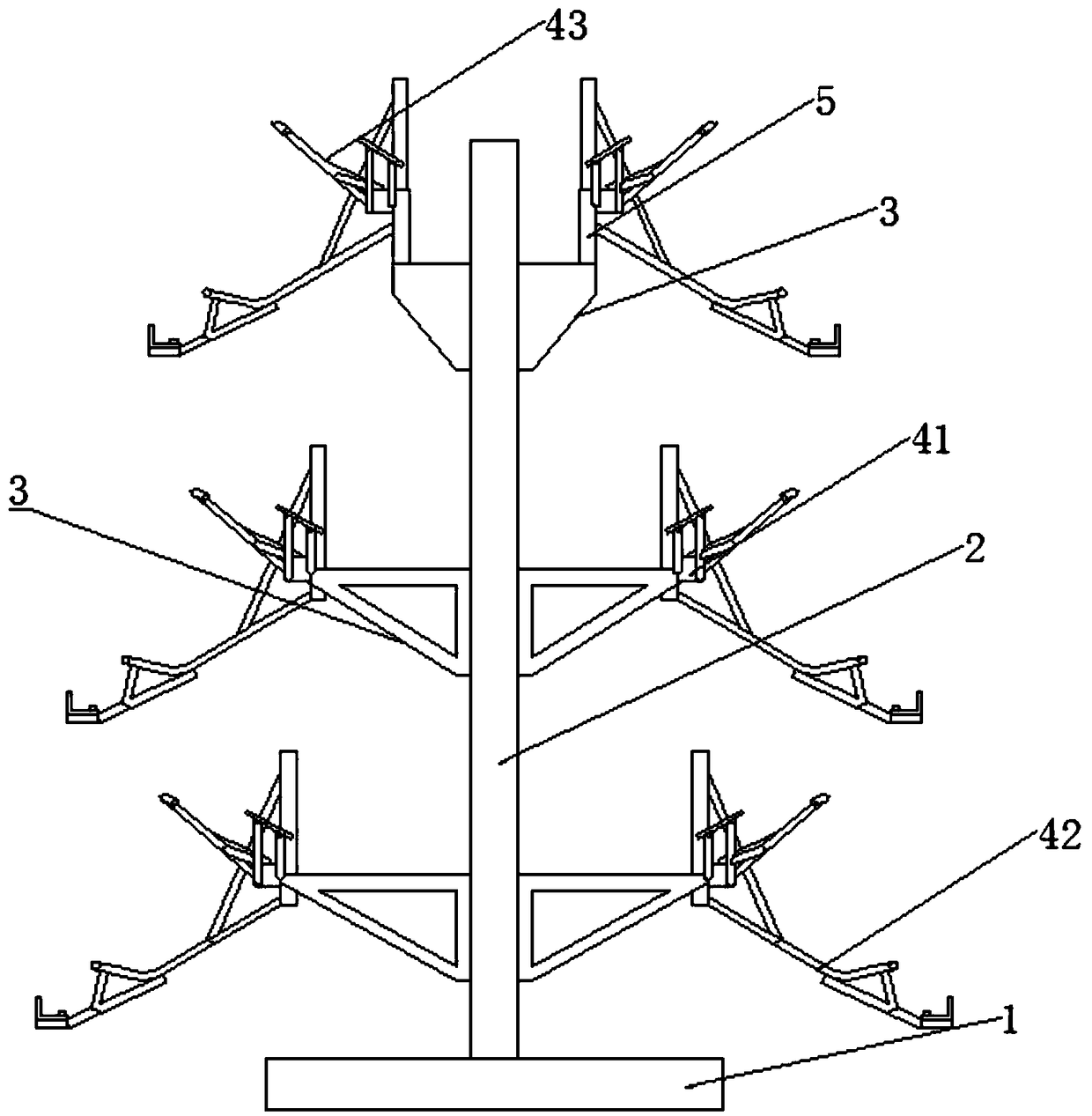
[0042] like Figure 1-3 As shown, the arrow indicates the direction of torque transmission, and the invention provides a kind of automobile front bumper spraying hanger, including a base 1, a foundation column 2 installed on the base 1 and fixed on the base from top to bottom Several hanger assemblies 4 on the foundation column 2. The foundation columns 2 are vertically fixed on the fixed beams 41 in pairs. There are several hanger assemblies 4 that can be arranged on the corresponding foundation column 2 from top to bottom, so as to realize spraying on three or more than three automobile front bumpers at the same time, and improve production efficiency.
[0043] Several component mounting plates 3 are fixed on the foundation column 2 from top to bottom, and the fixed beam 41 is fixed on the protruding end of the component mounting plate 3. The component mounting plate 3 includes a triangular plate or a right-angled trapezoidal plate. The length of the horizontal portion of ...
Embodiment 2
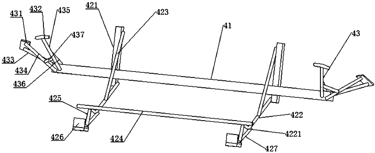
[0050] like Figure 4 As shown, the structural difference between this embodiment and Embodiment 1 lies in the structure of the front bracket 42 . In this embodiment, the front bracket 42 includes a front column 421, a first force rod 422, a reinforcing rod 423, a front profiling beam 424 and a second force rod 427; the first force rod 422 is fixed on the front column 421 And protruding obliquely downward, the protruding part has an upwardly curved bending part 4221; the reinforcing rod 423 is used to connect the front column 421 and the first force rod 422; the front profiling beam 424 is connected with the front of the car The bumper is matched and fixed on the end of the curved part 4221; the second force rod 427 is fixed on the first force rod 422, and the end has a profiling clip that blocks the front bumper of the automobile 426.
[0051] The second force receiving rod 427 is fixed on the upper surface of the first force receiving rod 422 and protrudes obliquely forwar...
Embodiment 3
[0053] like Figure 5 As shown, the difference in structure between this embodiment and Embodiment 2 lies in the structure of the fixed beam 41 and the connection method between the side bracket 43 and the fixed beam 41 . The fixed beam 41 includes a beam body 411 and side bracket fixing sleeves 412 slidingly sleeved on the two ends of the beam body 411. The tightening bolt 413 of the main support rod 435 , the secondary support rod 436 , the front support rod 434 and the rear support rod 433 are all fixed on the side bracket fixing sleeve 412 . The position of side support 43 can be adjusted like this, and the difference between some model bumpers is the change of their side and frontal relative position, and the present invention can adapt by adjusting side support fixing cover 412, has enlarged the scope of application of this hanger.
[0054] In each of the above-mentioned embodiments, a rubber layer or a similar elastic material layer can also be set on the surfaces of t...
PUM
 Abstract
Description
Claims
Application Information
 - R&D
- Intellectual Property
- Life Sciences
- Materials
- Tech Scout
- Unparalleled Data Quality
- Higher Quality Content
- 60% Fewer Hallucinations
Browse by: Latest US Patents, China's latest patents, Technical Efficacy Thesaurus, Application Domain, Technology Topic, Popular Technical Reports.
© 2025 PatSnap. All rights reserved.Legal|Privacy policy|Modern Slavery Act Transparency Statement|Sitemap|About US| Contact US: help@patsnap.com