

Pressure type gang drill self-locking mechanism
A pneumatic, self-locking technology, applied to fixed drilling machines, etc., can solve the problems of easy retraction of the rotating shaft, large air pressure, affecting the processing depth of the drill bit, etc., to ensure the consistency of the drilling depth and reduce the air pressure. Dosage and the effect of improving product quality
Active Publication Date: 2019-03-01
苏州格勒普机械有限公司
View PDF10 Cites 0 Cited by
- Summary
- Abstract
- Description
- Claims
- Application Information
AI Technical Summary
Problems solved by technology
This pneumatic drilling structure needs to supply air to the cylinder all the time after the rotating shaft is lowered so that the rotating shaft is in the working position. The tool retracts, which affects the processing depth of the drill bit to the hole position, and it is difficult to ensure the quality and consistency of the drilling depth
Method used
View moreImage
Smart ImageViewing Examples

Examples
Embodiment approach
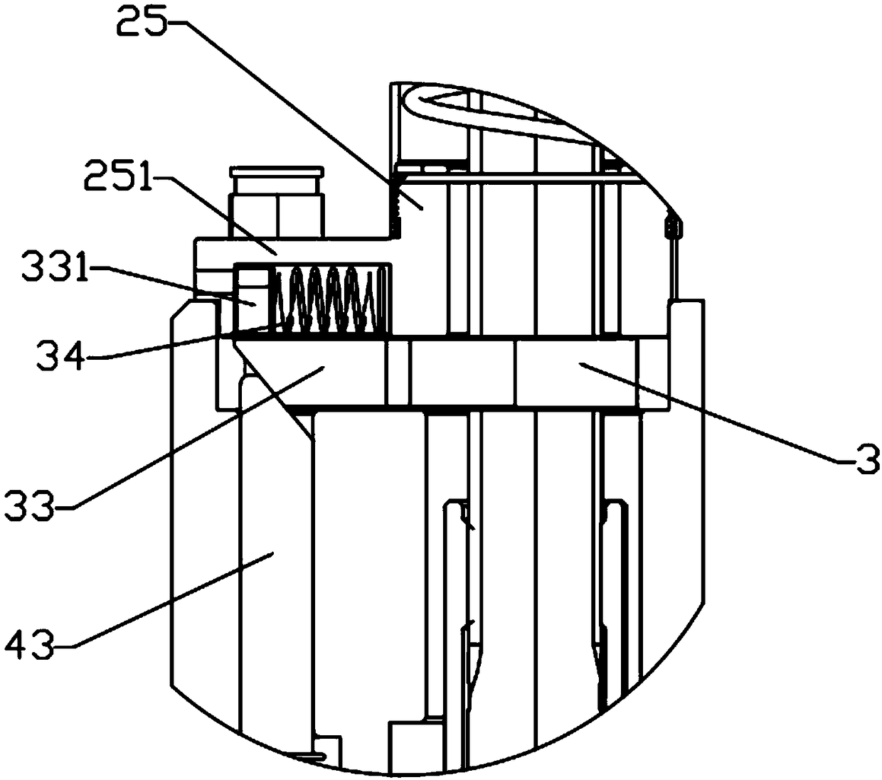
[0055] 作为本发明的另一种实施方式,所述解锁驱动机构为固定于所述固定架上的电磁铁组件5,该电磁铁组件包括固定于所述固定架上的电磁壳体51、一端置于所述电磁壳体内且另一端伸出该电磁壳体的电磁推杆52,以及套设于所述电磁推杆一端外的第三复位弹簧53,所述电磁壳体内设有与电源连接的线圈绕组,该线圈绕组通电时,所述电磁推杆推动所述侧移滑块向该侧移滑块的内端方向移动以将第一气缸轴解锁。
[0056] 所述电磁铁组件的电磁壳体平行于所述上下气缸的第一气缸体设置,所述电磁推杆垂直于所述侧移滑块且二者之间通过斜面接触。或者,所述电磁组件的电磁壳体垂直于所述上下气缸的第一气缸体设置,所述电磁推杆另一端抵紧于所述侧移滑块的外端面。
[0057] 该电磁铁组件的结构示意图参阅 Figure 7A , 7B ,其驱动解锁的具体工作过程如下:
[0058] 当需要解锁时,线圈绕组通电,电磁推杆52向外运动推动侧移滑块33向右运动,从而实现第一气缸轴23的解锁。解锁完成后,线圈绕组断电,电磁推杆52在第三复位弹簧53的作用下回复至初始位置。
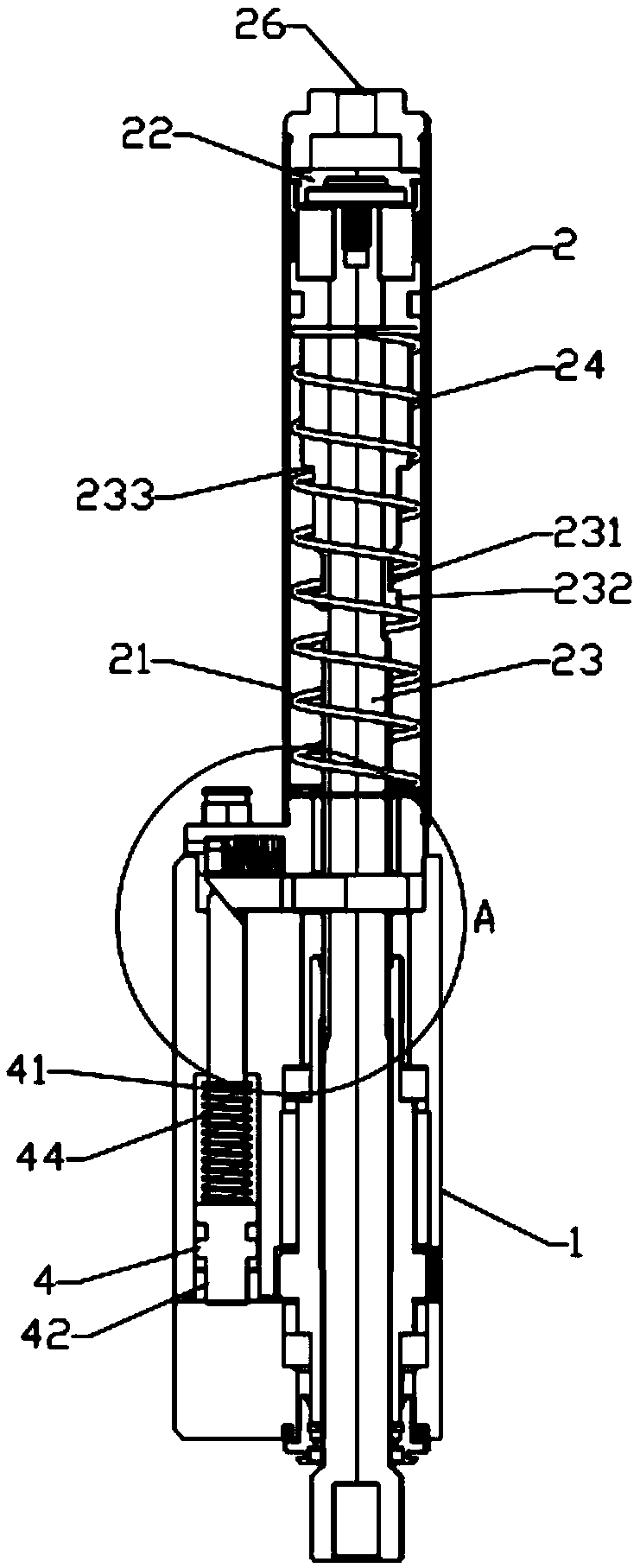
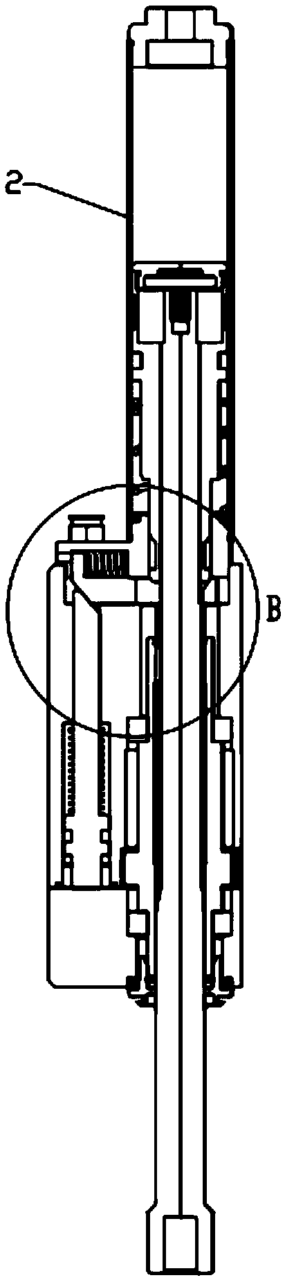
[0059] 由此可见,该气压式排钻自锁机构通过在每个钻头组件一侧设置自锁机构,可以对下降后的气缸轴进行锁定,当需要使用气缸轴连接的上下活动旋转轴及钻头进行加工作业时,只要对上下气缸进行入气约1.5秒,本机构既可对气缸轴进行锁定并断气加工,改善之前的机构在加工时,需要持续进气方能做到加工需求,不仅大大减少了气压用量,而且采用自锁机构将上下活动旋转轴锁定后,不会发生退刀现象,钻孔深度一致性得到保证,从而有效提高产品品质。
Login to View More PUM
 Abstract
The invention discloses a pressure type gang drill self-locking mechanism which comprises a fixing rack and a vertical air cylinder arranged on the fixing rack. The vertical air cylinder comprises a first air cylinder body, a first piston, a first air cylinder shaft, a first reset spring and a first fixing base, wherein the periphery of the first air cylinder body is provided with a lateral movement assembly, the lateral movement assembly is provided with an annular sleeve and a lateral movement slide block, and an annular oblique plane opening outwards is formed in the upper side edge of theinner side face, away from the lateral movement slide block, of the annular sleeve. A side locking spring is arranged between the outer end of the lateral movement slide block and the first fixing base. The outer side face of the upper end of the first air cylinder shaft is provided with a clamping groove and a positioning clamp point, and the lower end edge of the clamping groove outwards protrudes to form a clamping tenon. The fixing rack is provided with an unlocking drive mechanism. When the pressure type gang drill self-locking mechanism executes machining operation, the air cylinder shaft can be locked and gas stop machining can be executed only by executing gas introduction for the vertical air cylinder for 1.5 minutes, and the machining demand, which can be met by an existing mechanism through continuous gas feeding during machining, is met.
Description
technical field [0001] The invention belongs to the technical field of drill row equipment, and in particular relates to a pneumatic drill row self-locking mechanism. Background technique [0002] At present, in the furniture manufacturing industry, the connection of panel furniture and the installation of hardware accessories mostly require drilling holes on the surface of the panels. The drilling equipment is generally a woodworking machine or a drilling machine with a pneumatic drill. However, the existing pneumatic drill row structure has no self-locking function, and only the cylinder drives the rotating shaft that needs to work to descend, and after descending, the returning spring realizes the rising and reset of the rotating shaft. This pneumatic drilling structure needs to supply air to the cylinder all the time after the rotating shaft is lowered so that the rotating shaft is in the working position. The tool retracts, thereby affecting the processing depth of the...
Claims
Login to View More Application Information
Patent Timeline
 Patent Type & AuthorityApplications(China)
IPC IPC(8): B27C3/02
CPCB27C3/02Y02P70/10
Inventor萧进雄
Owner苏州格勒普机械有限公司