A compartment layering device

A technology of layered devices and carriages, applied in the superstructure of trucks, motor vehicles, vehicle parts, etc., can solve the problems of unsmooth operation, increased operation time, slightly inclined positioning track, etc., so as to achieve smooth movement and lift Stability, weight saving effect

Active Publication Date: 2020-09-01
ZHEJIANG TOPSUN LOGISTIC CONTROL CO LTD
View PDF6 Cites 2 Cited by
  • Summary
  • Abstract
  • Description
  • Claims
  • Application Information

AI Technical Summary

Problems solved by technology

During the use of this structure, there will be the following disadvantages: since the support plate and the two support beams are fixedly connected in the device, during the adjustment process, the support plate and the two support beams are adjusted simultaneously
However, there is a fit gap between the supporting beam and the fastening piece, and there is also a fit gap between the fastening piece and the positioning track. The superimposition of the two fit gaps makes it difficult for the operator to ensure that the two The fastening parts on the support beam can slide in the middle of the corresponding positioning track, so during the operation, there will be jamming, which will cause the operation process to be unsmooth and greatly increase the operation time
At the same time, during the installation process of the positioning track, the positioning track will be slightly inclined due to the deviation of the positioning track installation accuracy, so that the distance between the two positioning tracks on the inner wall of the same side of the car will appear wide at the top and narrow at the bottom or narrow at the top and wide at the top. Case
At this time, since the distance between the two supporting beams cannot be changed during the adjustment process of the device, the supporting beams will also jam during the adjustment process, making the operation not smooth

Method used


Image

  • A compartment layering device
  • A compartment layering device
  • A compartment layering device

Examples


Embodiment 1

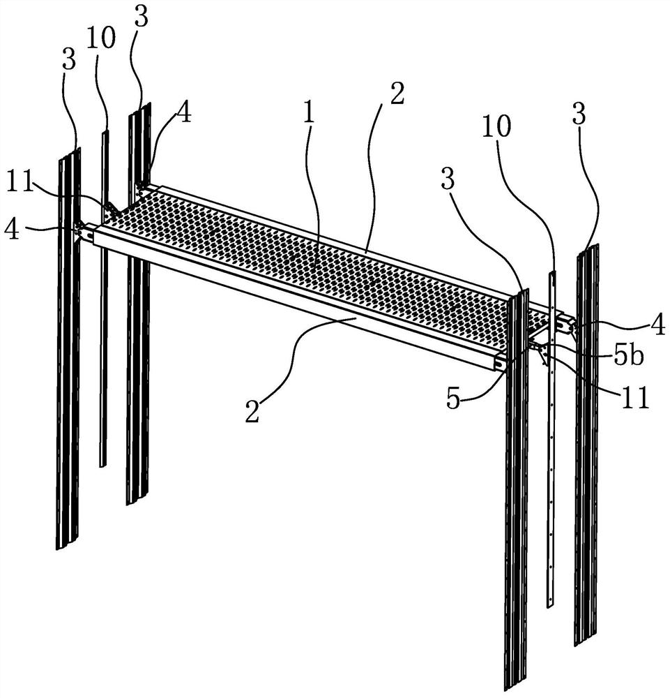
[0045] Such as figure 1 As shown, the layering device of the compartment includes a support plate 1, four main vertical rails 3, two auxiliary vertical rails 10, two support beams 2 parallel to each other and arranged at intervals, the support plate 1 is in the shape of a rectangular plate, Wherein two main vertical rails 3 and an auxiliary vertical rail 10 are fixed on the left inner wall of the compartment, and the other two main vertical rails 3 and the auxiliary vertical rail 10 are fixed on the right inner wall of the compartment, and four The two main vertical rails 3 are opposite to each other, and the two auxiliary vertical rails 10 are opposite to each other and opposite to the two ends of the support plate 1 respectively. The two ends of the support plate 1 are at a certain distance from the adjacent auxiliary vertical rail 10, so that a certain space is reserved between the two ends of the support plate 1 and the inner wall of the carriage. Hold the end of the supp...

Embodiment 2

[0056] The structure and principle of this embodiment are basically the same as that of Embodiment 1, the difference is that: Figure 13 As shown, the bottom surfaces of the two long sides of the support plate 1 rest on the top surfaces of the two support beams 2 respectively, and there are protrusions on the top surfaces of the support beams 2 that abut against the side walls of the two long sides of the support plate 1. 2b.

Embodiment 3

[0058] The structure and principle of this embodiment are basically the same as that of Embodiment 1, the difference is that: Figure 14 As shown, the connection assembly includes two support tubes 12, and the two support tubes 12 are respectively arranged at the bottom of the two ends of the support plate 1. The support tube 12 and the reinforcing beam 1b adopt the same connection structure as that of the first embodiment, and each support tube 12 A telescopic rod 5b is slidably arranged inside, and the outer end of the telescopic rod 5b is hinged with a locking part 2 11 .


PUM


Abstract

The invention provides a layering device of a compartment and belongs to the technical field of logistics appliances. A situation that the layering device of the compartment is easy to cause rail clamping in the operation process in the prior art is avoided. The layering device of the compartment comprises a supporting plate, two supporting cross beams and main vertical tracks, wherein the supporting cross beams are parallel to each other and arranged in a spaced manner; the main vertical tracks are fixedly connected to the left and right internal side walls of the compartment; locking piecesI slidingly connected with the main vertical tracks are correspondingly arranged at the two ends of each supporting cross beam; the locking pieces I can be located in different height positions on themain vertical tracks; the supporting plate is separately arranged between the two supporting cross beams and can be separated relative to the two supporting cross beams; a connecting component used for supporting the supporting plate is slidingly connected to the internal wall of the compartment; the connecting component can be located in different height positions on the internal wall of the compartment; the supporting plate can move up and down relative to the connecting component; and the front and rear side edges of the supporting plate can correspondingly prop against the two supportingcross beams. The layering device of the compartment has the advantages of smooth operation and stable supporting.

Description

technical field [0001] The invention belongs to the technical field of logistics equipment and relates to a compartment layering device. Background technique [0002] The layering device is applied in the compartment to make the inner space of the compartment form double or multi-layered devices. The layering device in the compartment generally includes two supporting beams parallel to each other and a supporting plate fixed on the two supporting beams. Both ends of the supporting beams are fastened with fasteners. At the same time, vertical rails are arranged on the inner wall of the compartment. , the locking pieces at the ends of the supporting beams are respectively connected to a vertical rail. The connection between the existing vertical rails and the locking pieces is not precisely matched sliding, and the locking pieces and the vertical rails are also connected There will be a certain fit gap. And when the locking member moves up and down in the vertical track, the...

Claims


Application Information

Patent Timeline
Patent Type & Authority Patents(China)
IPC IPC(8): B62D33/04B60P7/14
CPCB60P7/14B62D33/04
Inventor 阮卜琴牛胜良
Owner ZHEJIANG TOPSUN LOGISTIC CONTROL CO LTD
Why Eureka
Try Eureka