Diaphragm slitting machine

A technology of slitting machine and diaphragm, which is applied in the direction of winding strips, sending objects, cleaning methods and utensils, etc., can solve the problems of difficult replacement of cutters and difficult cutting, etc., achieve easy replacement, improve production efficiency, and ingenious mechanism coordination Effect

Pending Publication Date: 2019-03-01
WUXI LEAD INTELLIGENT EQUIP CO LTD
View PDF6 Cites 4 Cited by
  • Summary
  • Abstract
  • Description
  • Claims
  • Application Information

AI Technical Summary

Problems solved by technology

In the traditional slitting machine, the cutter assembly mostly adopts a straight knife, which is not easy to cut, and the cutter is not easy to replace

Method used


Image

  • Diaphragm slitting machine
  • Diaphragm slitting machine
  • Diaphragm slitting machine

Examples


Embodiment Construction

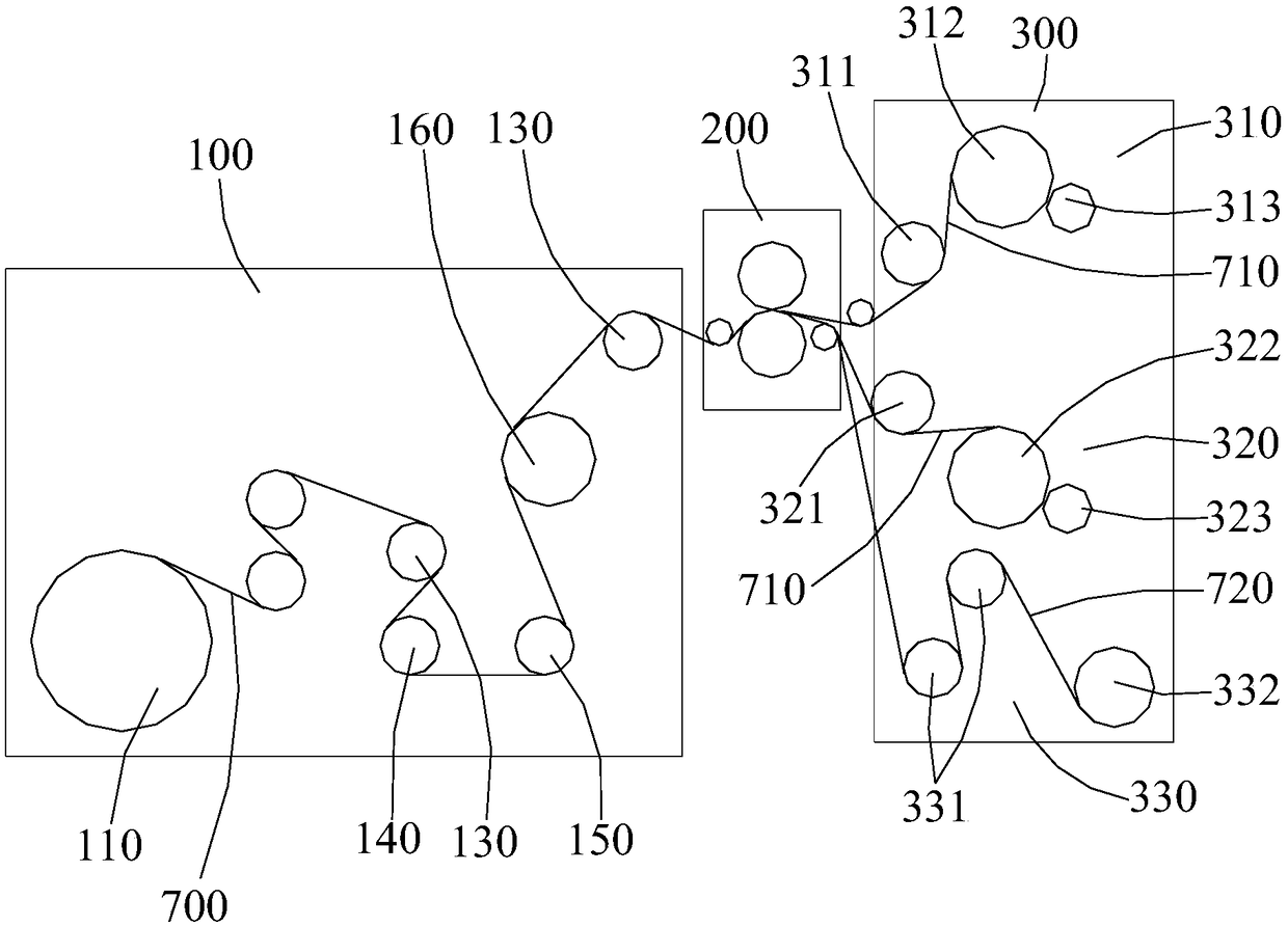
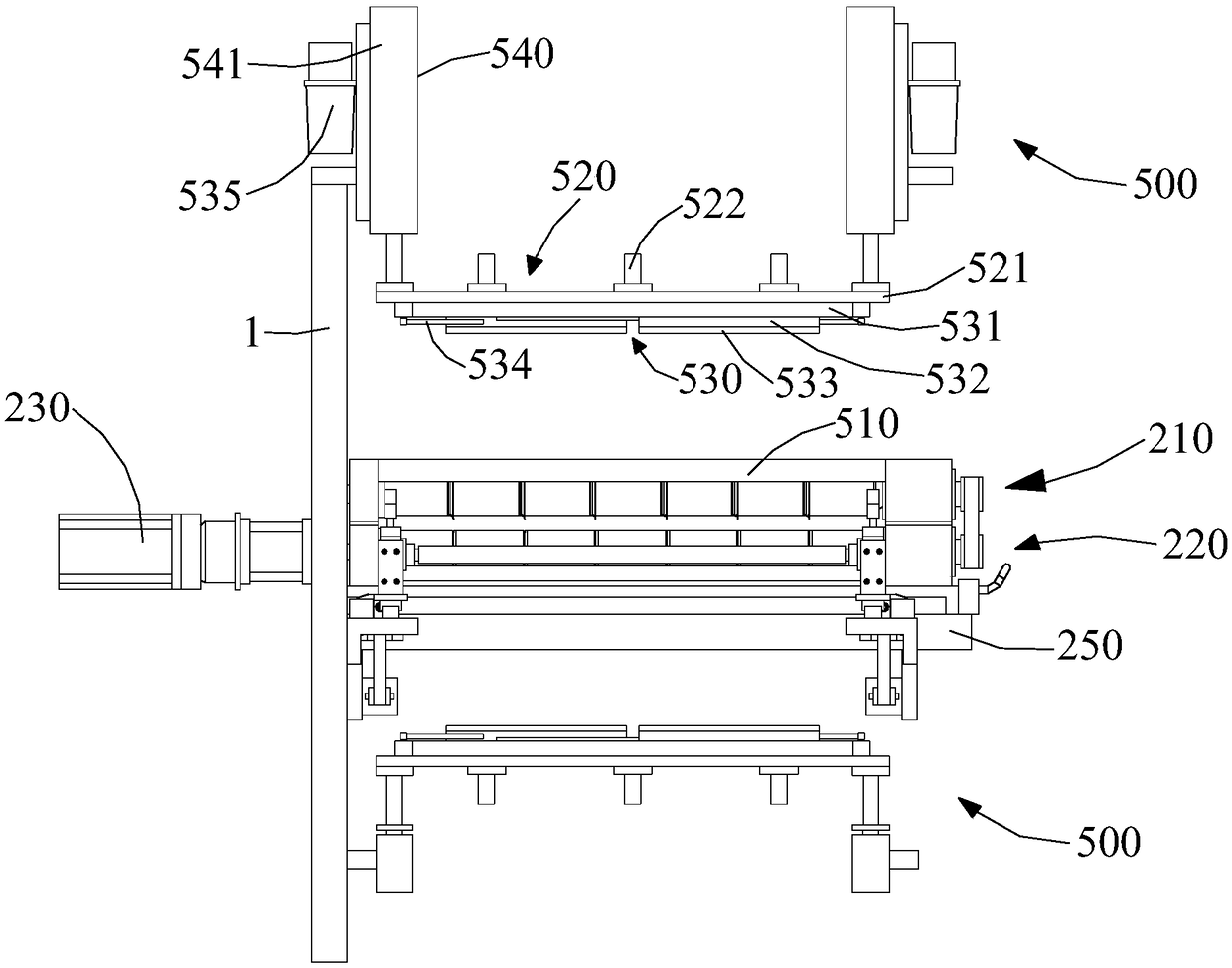
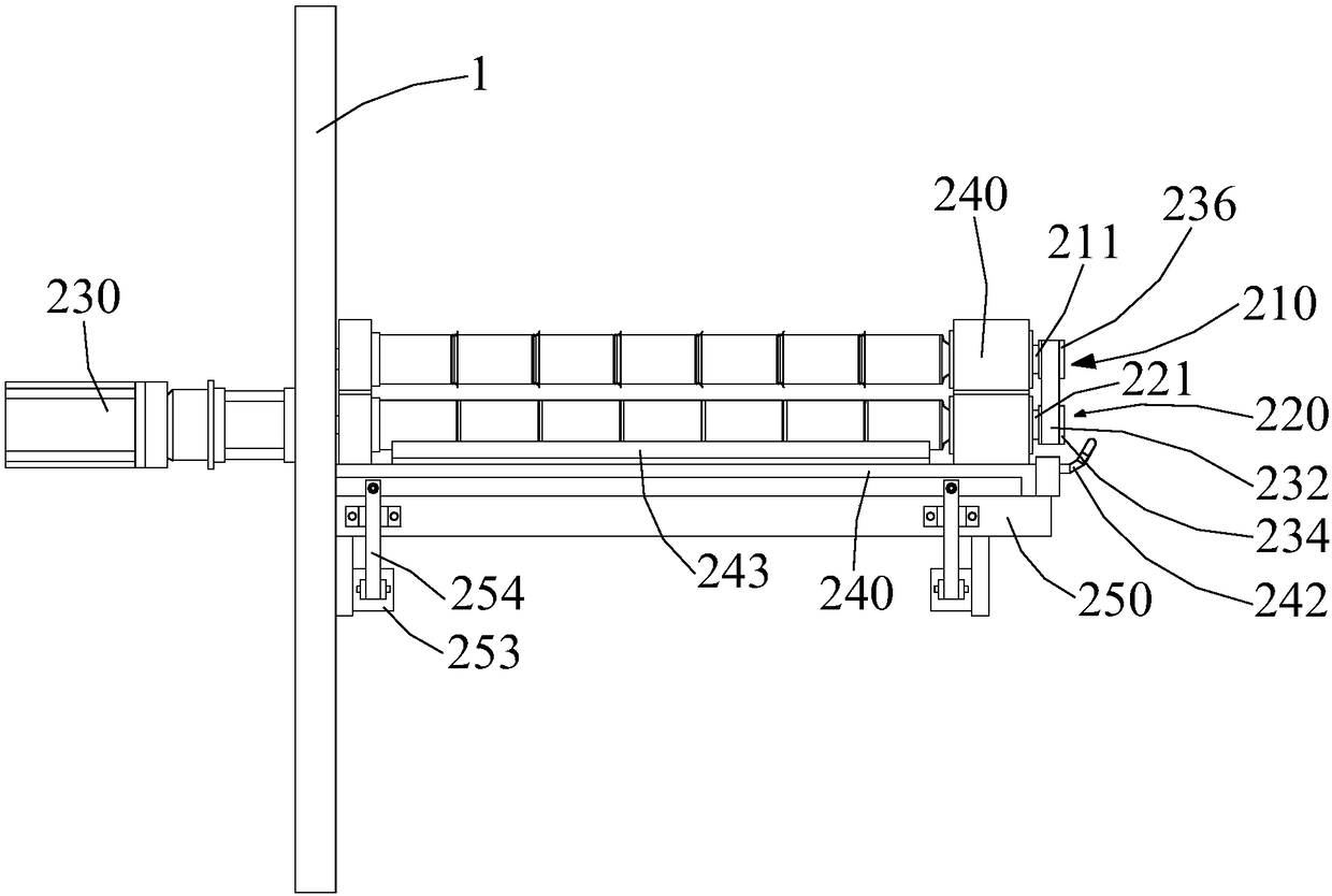
[0020] Please refer to Figure 1 to Figure 5 As shown, the present invention discloses a diaphragm slitting machine for cutting a diaphragm substrate 700 into a plurality of strip-shaped diaphragm strips 710, which includes an unwinding mechanism 100, a cutting mechanism 200, a winding mechanism 300 and Two dust suction mechanisms 500 , one of which is disposed above the cutting mechanism 200 , and the other dust suction mechanism 500 is disposed below the cutting mechanism 200 .

[0021] see figure 1 As shown, the unwinding mechanism 100 includes a material roll 110 and a roller 140; the diaphragm base material 700 is wound on the material roll 110, and the material roll 110 is driven by a material roll driving device (not shown) to perform unwinding in a rotating manner. ; The released separator substrate 700 is guided into the cutting mechanism 200 via the roller 140 .

[0022] In order to output the diaphragm substrate 700 better, the unwinding mechanism 100 also include...


PUM


Abstract

The invention discloses a diaphragm slitting machine. The diaphragm slitting machine comprises a slitting mechanism, wherein the slitting mechanism comprises an upper cutter assembly, a lower cutter assembly, a cutter driving device used for driving the upper cutter assembly and the lower cutter assembly to rotate synchronously, a cutter rest and a cutter die bottom plate assembly, wherein the cutter rest and the upper cutter assembly as well as the lower cutter assembly are movably arranged on the cutter die bottom plate assembly. The design is achieved thus, so that switching of cutters is easy, simple and convenient.

Description

technical field [0001] The invention relates to the technical field of lithium battery automation equipment, in particular to a separator cutting machine. Background technique [0002] When making battery cells, it is necessary to separate the positive and negative electrodes with a separator to prevent short circuits caused by contact between electrodes of different polarities. According to the different cell specifications, the diaphragm base material needs to be cut to the required width according to the needs, and then the cut diaphragm strips are rolled into rolls, which is convenient for the later preparation of the cell. In the traditional slitting machine, the cutter assembly mostly adopts a straight knife, which is not easy to cut, and the cutter is not easy to replace. Contents of the invention [0003] The object of the present invention is to provide a diaphragm slitting machine which is convenient to replace the cutter. [0004] In order to achieve the above...

Claims


Application Information

Patent Timeline
Patent Type & Authority Applications(China)
IPC IPC(8): B65H35/02B65H20/02B65H23/26B65H18/10B08B5/04
CPCB65H18/10B65H20/02B65H23/26B65H35/02B08B5/04
Inventor 不公告发明人
Owner WUXI LEAD INTELLIGENT EQUIP CO LTD
Why Eureka
Try Eureka