
Air lift biologic generator for sewage treatment

A sewage treatment, air-lift technology, applied in the direction of biological water/sewage treatment, water/sludge/sewage treatment, water aeration, etc., to achieve the effect of easy collection and less trouble

Inactive Publication Date: 2019-03-01
林锋忠
View PDF0 Cites 0 Cited by
  • Summary
  • Abstract
  • Description
  • Claims
  • Application Information

AI Technical Summary

Problems solved by technology

[0004] In view of the deficiencies in the prior art, the purpose of the present invention is to provide an air-lift biogenerator for sewage treatment to solve the existing problems

Method used


Image

  • Air lift biologic generator for sewage treatment
  • Air lift biologic generator for sewage treatment
  • Air lift biologic generator for sewage treatment

Examples


Embodiment Construction

[0024] In order to make the technical means, creative features, goals and effects achieved by the present invention easy to understand, the present invention will be further described below in conjunction with specific embodiments.

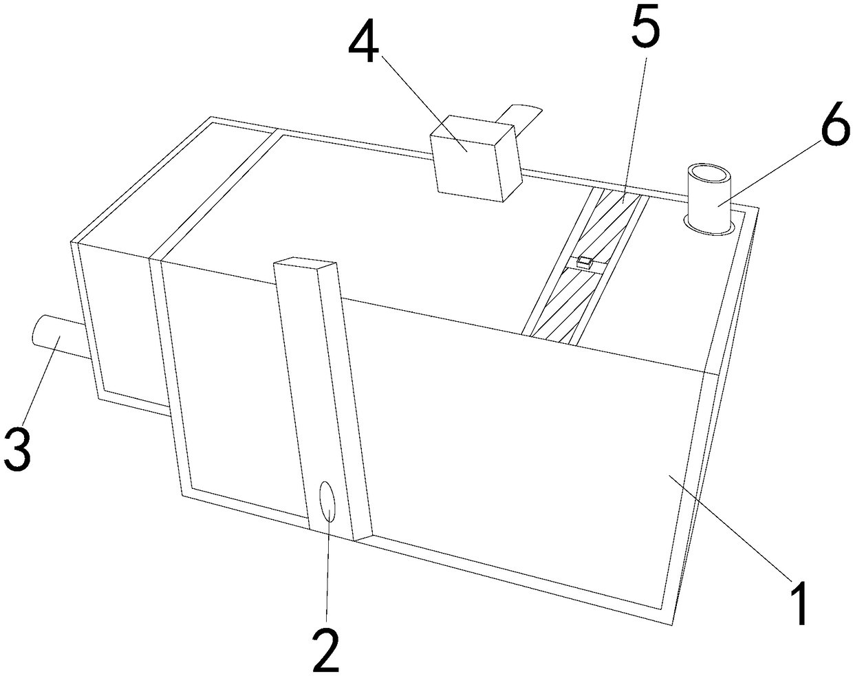
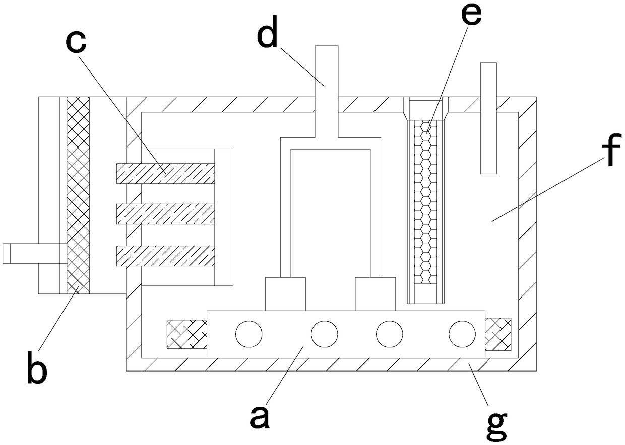
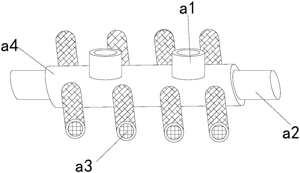
[0025] see Figure 1-Figure 6 , the present invention provides a technical scheme of air-lift biogenerator for sewage treatment: its structure includes: air-lift reaction box 1, defoamer 2, water outlet pipe 3, air pump 4, lifting upper cover 5, water inlet pipe 6. The outlet pipe 3 is installed on the left end of the air-lift reaction box 1 and fastened with the air-lift reaction box 1. The front side of the air-lift reaction box 1 is provided with a defoamer 2 and is locked with the defoamer 2. The upper right side of the air-lift reaction box 1 is provided with a water inlet pipe 6 and is fastened with the water inlet pipe 6. The upper side of the air-lift reaction box 1 is provided with a lifting upper cover 5, and the lifting upper cover 5 is...


PUM


Abstract

The invention discloses an air lift biologic generator for sewage treatment. The air lift biologic generator structurally comprises an air lift reaction box, a defoamer, a water outlet pipe, an air pump, a lifting upper cover and a water inlet pipe, wherein the water outlet pipe is arranged at the left end of the air lift reaction box and is buckled and connected with the air lift reaction box; the front side of the air lift reaction box is provided with the defoamer and is locked and connected with the defoamer; when the equipment is used, through the arrangement of a filler cabin mechanism,the condition that when an air inlet pump is closed, a part of sewage frequently and easily flows back into the air inlet pipe through a gap is avoided; because the water quality is poor, bacteria canbe easily generated in the air inlet pipe; the subsequent sewage conversion is not facilitated; fillers are directly thrown into a reaction tank by a traditional generator for adsorption reaction; when filler needs to be replaced, the operation cannot be performed in dead corners; the trouble of fishing-up is caused; the equipment can conveniently collect the filler while enabling the filler to fully exert an adsorption effect; water is effectively prevented from entering the air inlet pipe.

Description

technical field [0001] The invention relates to an air-lift biogenerator used for sewage treatment, which belongs to the field of biogenerators. Background technique [0002] Airlift bioreactors are divided into two categories: internal circulation and external circulation. Its fluidity is more uniform than other bioreactors, and its structure is simple. It can be used for process transformation and upgrading of existing sewage treatment plants. [0003] The existing technology has the following disadvantages: a part of the sewage often flows back into the intake pipe when the air intake pump is closed. Due to its poor water quality, bacteria are likely to be produced in the intake pipe, which is not conducive to the subsequent transformation of sewage, and the traditional generator will fill directly. Throw it in the reaction tank for adsorption reaction. Since the packing has a certain service life, when it is necessary to replace the packing, you need to open the upper co...

Claims


Application Information

Patent Timeline
Patent Type & Authority Applications(China)
IPC IPC(8): C02F3/00C02F3/10C02F3/02C02F7/00
CPCC02F3/00C02F3/02C02F3/10C02F7/00Y02W10/10
Inventor 林锋忠
Owner 林锋忠
Learn More