Slab culvert cast-in-situ roof truss type slip form system and construction method

A truss-type, slab-covered culvert technology, which is applied in the direction of buildings and road bottoms, can solve the problems of affecting the use function of the lower part of the slab culvert, affecting the stability of the roadbed, and long construction period, so as to reduce the number of equipment configurations and fast turnover , the effect of short time

Active Publication Date: 2019-03-01
德达交通建设发展集团有限公司
View PDF9 Cites 3 Cited by
  • Summary
  • Abstract
  • Description
  • Claims
  • Application Information

AI Technical Summary

Problems solved by technology

Although its structure is simple and construction is not difficult, it plays a very important role in the project. If its construction quality cannot be guaranteed, it will have a great impact on the stability of the subgrade, and eventually cause the road to collapse and affect the slab culvert. Lower use function
[0003] In view of this, in order to improve the deficiencies in the construction of traditional slab culverts, the long construction period, the stability of the roadbed and other issues

Method used


Image

  • Slab culvert cast-in-situ roof truss type slip form system and construction method
  • Slab culvert cast-in-situ roof truss type slip form system and construction method
  • Slab culvert cast-in-situ roof truss type slip form system and construction method

Examples


Embodiment Construction

[0040]The present invention will be further described below in conjunction with the examples. The description of the following examples is provided only to aid the understanding of the present invention. It should be pointed out that for those skilled in the art, without departing from the principle of the present invention, some improvements and modifications can be made to the present invention, and these improvements and modifications also fall within the protection scope of the claims of the present invention.

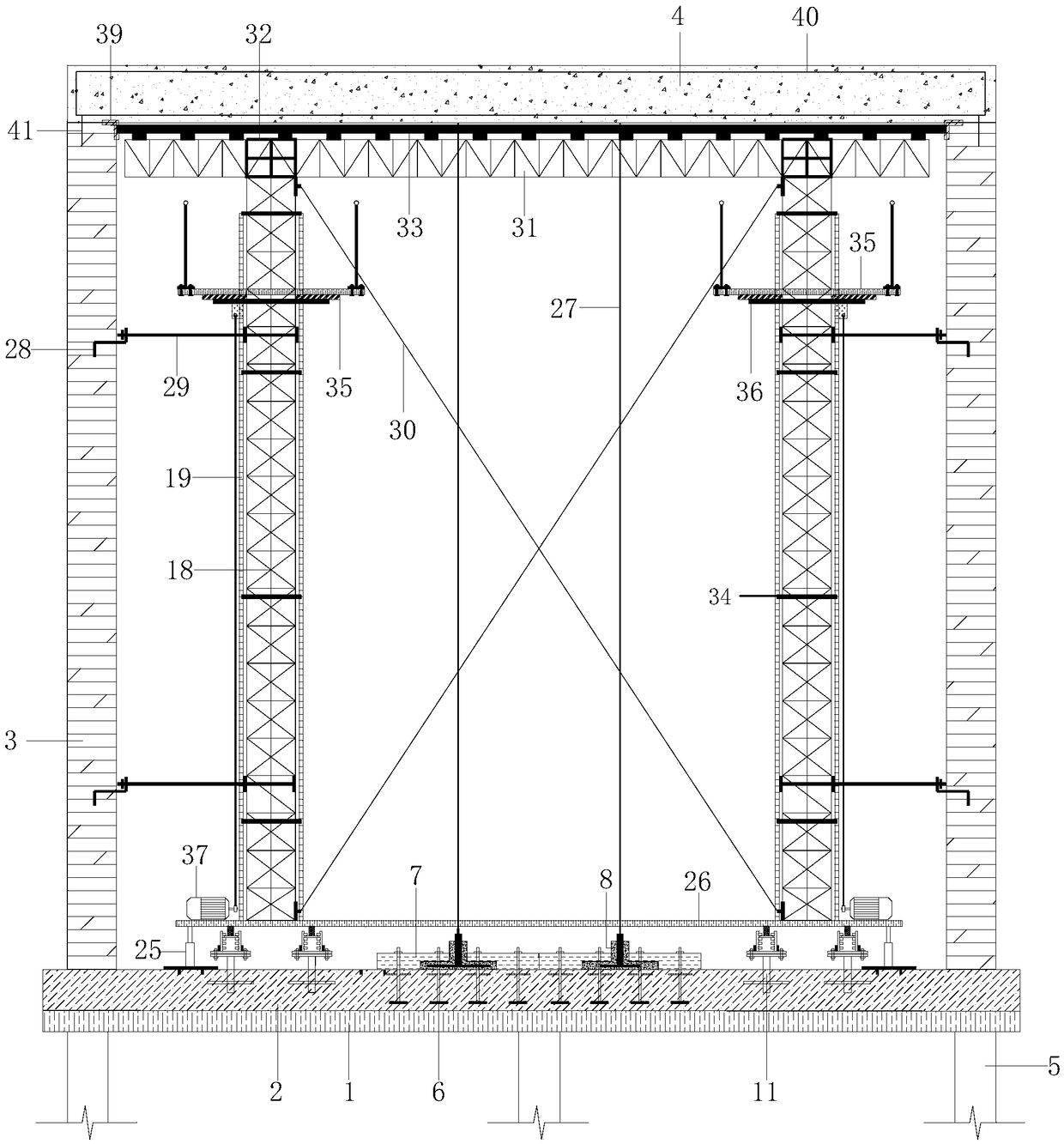
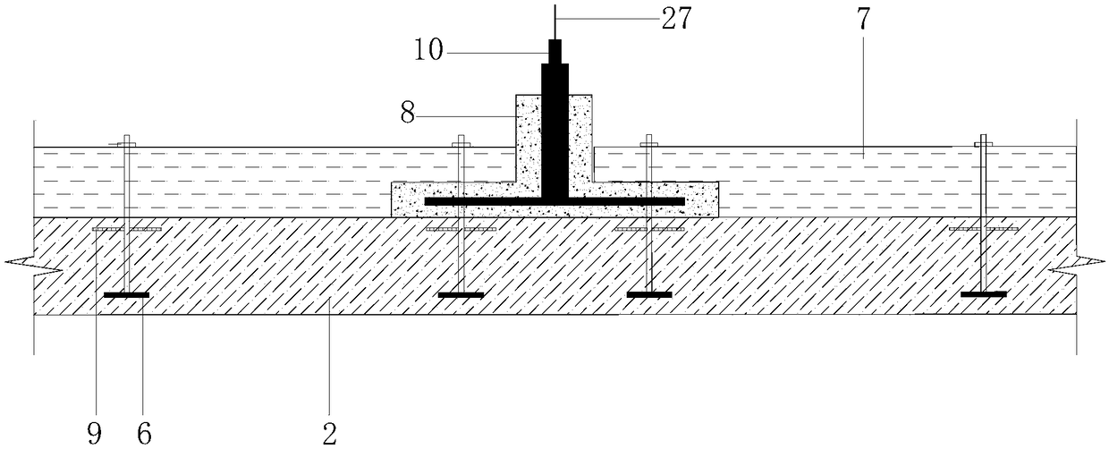
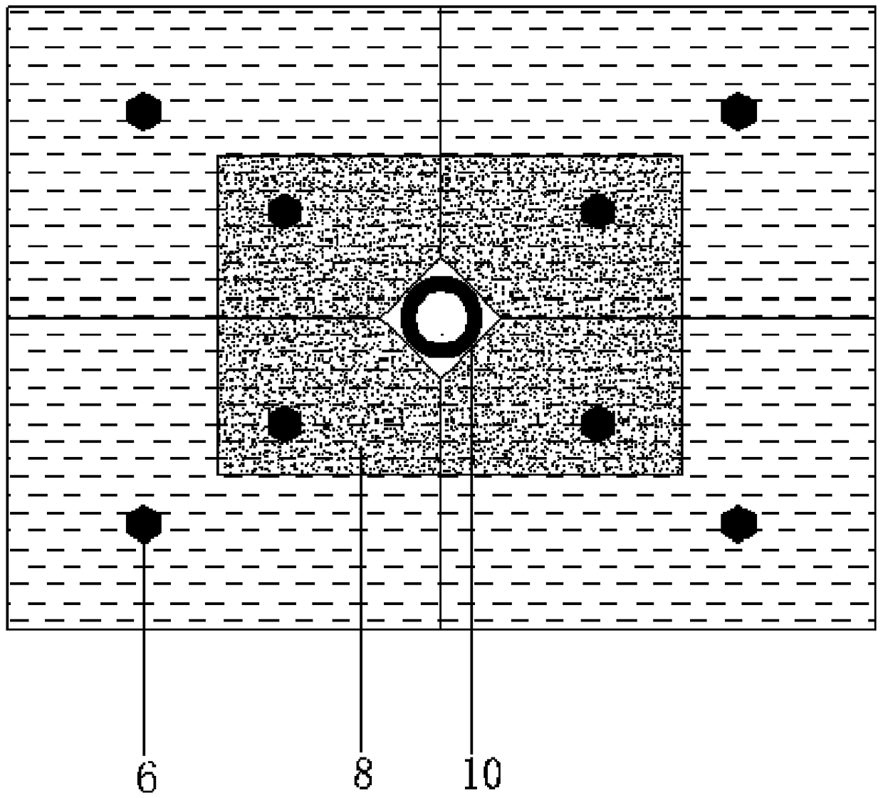
[0041] Such as Figure 1-11 As shown, the truss-type sliding form system for the cast-in-place roof slab of the cover culvert includes a cushion layer 1, a culvert bottom plate 2, a culvert side plate 3, a culvert top plate 4, foundation treatment piles 5, truss columns 18, and sliding attachment vertical rails 19. Integral counterforce preloading frame 21, integral jacking beam 26 and roof bottom mold 33; cushion layer 1 and culvert floor 2 are arranged on founda...


PUM


Abstract

The invention relates to a slab culvert cast-in-situ roof truss type slip form system. The slab culvert cast-in-situ roof truss type slip form system comprises a cushion course, a culvert bottom plate, culvert side plates, a culvert top plate, foundation treatment piles, truss uprights, a sliding adhesion vertical rail, an integral counter-force prepressing frame, an integral jacking cross beam and a top plate bottom die; the cushion course and the culvert bottom plate are arranged on the foundation treatment piles; a counter-force prepressing embedded piece and a bottom plate track embedded piece are embedded in the culvert bottom plate; a frame format type counter-force plate and an expanded counter-force disc are connected with the counter-force prepressing embedded piece; a channel steel ear plate is arranged at the upper part of the bottom plate track embedded piece; the upper part of the channel steel ear plate is connected with a pulley; an integral jacking cross beam is arranged at the upper part of the pulley; truss uprights are arranged at the upper part of the integral jacking cross beam; and the sliding adhesion vertical rails are arranged on the truss uprights. The slab culvert cast-in-situ roof truss type slip form system has the beneficial effects that the slab culvert top plate adopts a truss type slip form system, a unit truss is assembled outside, a top reinforcement cage is integrally molded and hoisted on site, and a sliding type operation platform is placed on the truss uprights and is combined and fixed by using overhanging channel steels and rotary supporting steel plates, and therefore, the construction speed can be increased.

Description

technical field [0001] The invention relates to a cover culvert cast-in-place roof formwork system and a construction method, in particular to a cover culvert cast-in-place roof truss-type sliding form system and a construction method. Background technique [0002] Culvert projects are an important node related to construction projects in highway and railway construction, and culvert projects account for the main components of highways and railways in terms of quantity and project cost. Especially in areas with complex terrain conditions such as mountainous areas, the cost of culvert engineering can account for more than 30% of the total project investment. Therefore, ensuring the quality and progress of culvert engineering construction is a key link related to smooth traffic. Compared with bridge engineering, the structural form of culverts is relatively simple, but it is also divided into various types according to its structural form and embedding method. Although its s...

Claims


Application Information

Patent Timeline
Patent Type & Authority Applications(China)
IPC IPC(8): E01F5/00
CPCE01F5/005
Inventor 王宗明赵洪建沈桂儒张孝东张银仙
Owner 德达交通建设发展集团有限公司
Why Eureka
Try Eureka