Splitting method of laminated assembly type pipe gallery

A prefabricated, pipe gallery technology, applied in water conservancy projects, artificial islands, underwater structures, etc., can solve the problems of long exposure time of potential safety hazards in foundation pits, increasing the difficulty of factory prefabrication, and high requirements for hoisting equipment. The effect of reducing the investment of steel bar operators, reducing the workload of binding, and improving the quality of waterproofing

Inactive Publication Date: 2019-03-01
THE 4TH CONSTR ENG CO LTD OF CHINA RAILWAY NO 4 ENG GRP +1
View PDF7 Cites 1 Cited by
  • Summary
  • Abstract
  • Description
  • Claims
  • Application Information

AI Technical Summary

Problems solved by technology

[0002] With the rapid development of the city, people's living standards are improving day by day, and the urban road network is becoming more and more developed. However, the laying of cables, optical cables, gas pipelines and other pipelines must have a supporting comprehensive pipe gallery. The traditional cast-in-place construction method has a long construction period. The hidden safety hazards of the foundation pit have been exposed for a long time and are greatly affected by weather factors. The construction progress is restricted, and it is a multi-process interspersed operation. The on-site civilized construction is poor, and it is not energy-saving and environmentally friendly.
[0003] At present, there is a construction method of segmentally prefabricated pipe joints, but this method prefabricates the comprehensive pipe gallery in sections. Because the cross-sectional size of the comprehensive pipe gallery is large, the weight of each section of the pipe joint is about 30 tons. Not only does it increase the difficulty of factory prefabrication, but it also requires very high requirements for on-site hoisting equipment. Generally, at least a 50-ton crane is required. During the construction process, there are great safety hazards, and there are many seams in the pipe gallery, which increases the difficulty of waterproofing the gallery body. Poor engineering quality control resulting in higher overall production and construction costs

Method used


Image

  • Splitting method of laminated assembly type pipe gallery
  • Splitting method of laminated assembly type pipe gallery
  • Splitting method of laminated assembly type pipe gallery

Examples


Embodiment Construction

[0020] Combine below Figure 1 to Figure 8 , the present invention is described in further detail.

[0021] A method for splitting a superimposed assembly pipe gallery, comprising the following steps:

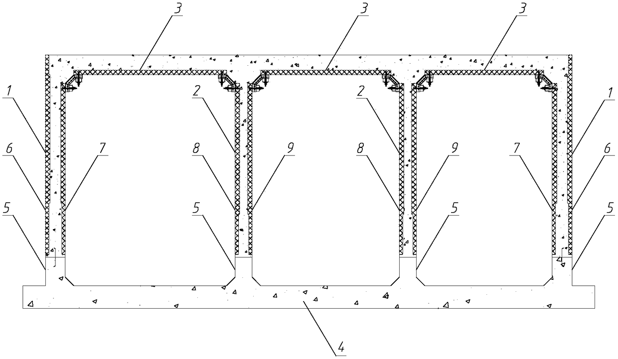
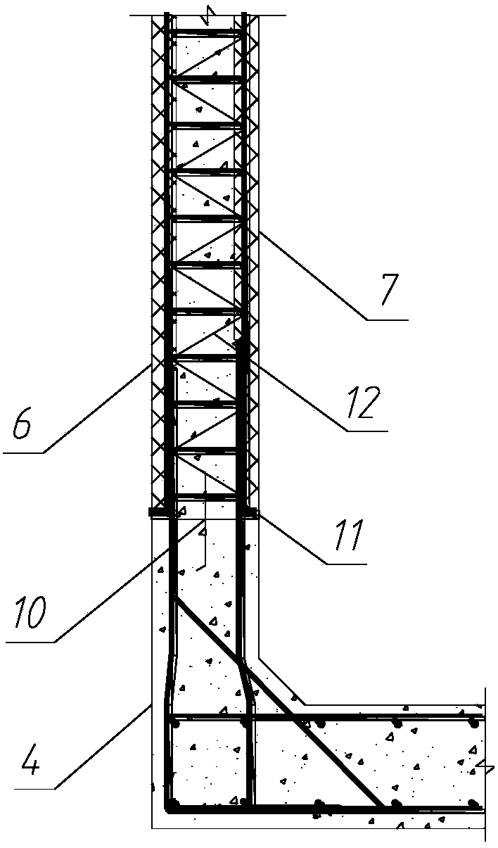
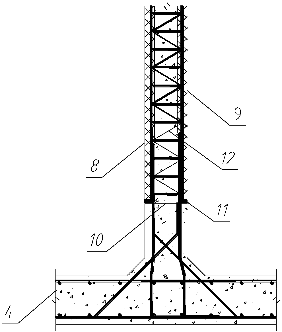
[0022] a. Divide the gallery body into several sections of pipe galleries, and according to the structural force characteristics of the pipe gallery, split each section of pipe gallery into superimposed double-layer wall panels, superimposed single-layer roof 3 and cast-in-place bottom slab 4, each section The pipe gallery has seven prefabricated components, including four superimposed double-layer wall panels and three superimposed single-layer roof panels 3, and the four superimposed double-layer wall panels include two superimposed double-layer exterior wall panels 1 and two A superimposed double-layer partition wall panel 2;

[0023] b. The cast-in-place bottom plate 4 is connected to the two superimposed double-layer exterior wall panels 1 and the two superimposed double...


PUM


Abstract

The invention relates to a splitting method of a laminated assembly type pipe gallery. The splitting method comprises the following steps that a, a gallery body is divided into a plurality of tube galleries, wherein each section of pipe gallery is divided into a laminated double-layer wallboard, a laminated single-layer top plate and a cast-in-place bottom plate; b, the cast-in-place bottom plateis connected with the laminated double-layer wallboard through an upward-turning guide wall arranged on the side edge of the width direction of the cast-in-place bottom plate, the laminated single-layer top plate is connected with the laminated double-layer wallboard through a U-shaped sleeve hoop to form a hidden beam connection; c, respectively grooves and joints are arranged between the overlapped type single-layer top plates and the overlapped type double-layer wall plates of the adjacent two-section pipe gallery, then every two adjacent tube galleries are connected through a hidden beam arranged in the groove and a hidden column at the joint position, and a plurality of sections of pipe gallery which are connected are integrally poured to form a gallery body. According to the splitting method, the weight of the single component is light, the difficulty of factory prefabrication and on-site assembly is reduced, the requirements for hoisting equipment are reduced, and the advantagesof saving the production cost, the transportation cost and the on-site construction cost are achieved.

Description

technical field [0001] The invention relates to the field of underground pipe galleries, in particular to a splitting method of a superimposed and assembled pipe gallery. Background technique [0002] With the rapid development of the city, people's living standards are improving day by day, and the urban road network is becoming more and more developed. However, the laying of cables, optical cables, gas pipelines and other pipelines must have a supporting comprehensive pipe gallery. The traditional cast-in-place construction method has a long construction period. The hidden safety hazards of the foundation pit have been exposed for a long time and are greatly affected by weather factors. The construction progress is restricted, and it is a multi-process interspersed operation. The on-site civilized construction is poor, and it is not energy-saving and environmentally friendly. [0003] At present, there is a construction method of segmentally prefabricated pipe joints, but ...

Claims


Application Information

Patent Timeline
Patent Type & Authority Applications(China)
IPC IPC(8): E02D29/045
CPCE02D29/045E02D29/10
Inventor 朱晓勇姚东方吕朝乾王根杰陈小文张威伍军王圣涛董燕囡刘永丽高媛
Owner THE 4TH CONSTR ENG CO LTD OF CHINA RAILWAY NO 4 ENG GRP
Why Eureka
Try Eureka