Door opener for opening cabinet type hinged door

A door-opening device and side-opening technology, applied in door/window fittings, wing leaf operating mechanisms, buildings, etc., can solve the problem that two door leaves cannot be opened independently and can be switched each other, and cannot well meet people's individual needs and other problems. , to achieve the effect of improving automatic control performance, simple structure and small space occupation

Pending Publication Date: 2019-03-01
TONELUCK PROD TECH (HUIZHOU) CO LTD
View PDF0 Cites 2 Cited by
  • Summary
  • Abstract
  • Description
  • Claims
  • Application Information

AI Technical Summary

Problems solved by technology

[0004] However, there are still many deficiencies in the existing door opening device for auxiliary side-by-side door opening.
Among them, most of the existing door opening devices that assist the opening of the door open two doors at the same time, and the opening of the two doors cannot be carried out independently or switched between each other, which cannot meet people's individual needs well, and only one of the doors needs to be opened separately. In some cases, this kind of door opening device that opens two doors at the same time will bring more inconvenience

Method used


Image

  • Door opener for opening cabinet type hinged door
  • Door opener for opening cabinet type hinged door
  • Door opener for opening cabinet type hinged door

Examples


Embodiment 1

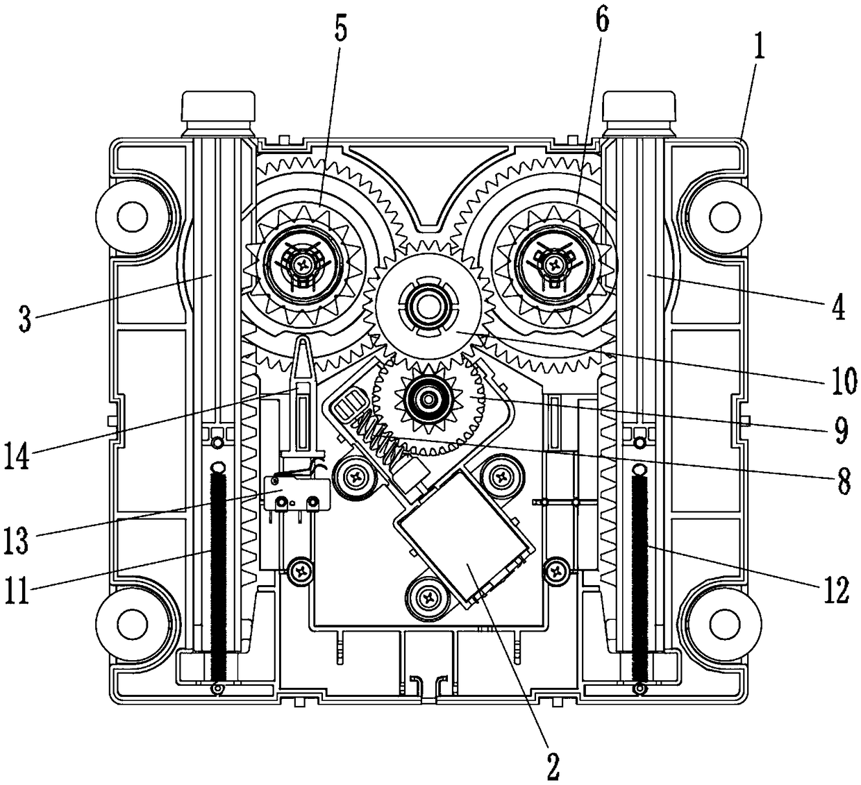
[0034] A door-opening device for opening cabinet-type side-by-side doors, mainly used for independent opening of the two door leaves of the side-by-side door. The schematic diagram of its overall internal structure can be found in figure 1 As shown, the door opening device includes a housing 1 , and a power source mechanism 2 , a first push rod 3 and a second push rod 4 arranged in the housing 1 . The casing 1 has accommodating cavities extending upwards from the bottom thereof for arranging various components, and the accommodating cavities are based on the relationship and / or communication between the components.

[0035] The first push rod 3 and the second push rod 4 are used to correspondingly push and open the two door leaves of the side-by-side door, the first push rod 3 and the second push rod 4 are symmetrically arranged on the left and right sides of the housing 1, and the second push rod The ends of the first push rod 3 and the second push rod 4 close to the door body ...

Embodiment 2

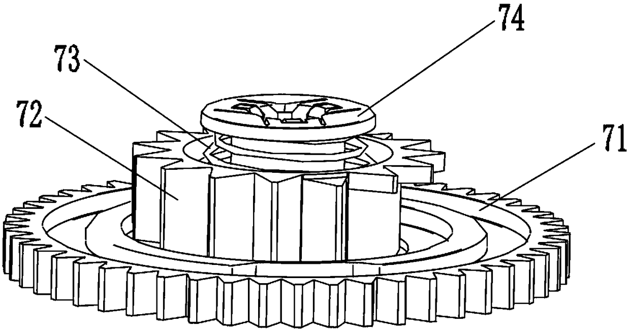
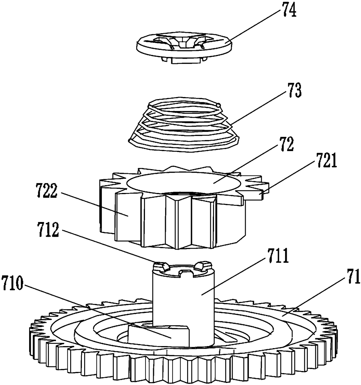
[0046] A door-opening device for opening cabinet type side-by-side doors, which is the same as Embodiment 1, the difference is that in this embodiment, see figure 1 As shown, a first micro switch 13 is installed outside the first one-way clutch device 5 for sensing the rotation of the first one-way clutch device. Further, see Figure 4a with Figure 5As shown, wherein, the periphery of the spiral step 710 of the driving gear 71 of the one-way clutch device is also distributed with a circle of induction transmission bosses 713 protruding axially along the drive gear 71; the radially outer surface of the induction transmission bosses 713 There are groove gaps 714 that are curved on both sides; the driving rod 131 of the micro switch 13 abuts against one end surface of the external force transmission part 14, and the other end of the external force transmission part 14 extends into the diameter of the induction transmission boss 713. In the groove notch 714 on the outer side, a...


PUM


Abstract

The invention discloses a door opener for opening a cabinet type hinged door. The door opener comprises a shell (1), a power source mechanism (2) arranged in the shell (1), and a first push rod (3) and a second push rod (4) for correspondingly pushing to open two door leaves of the hinged door. The first push rod (3) and the second push rod (4) are symmetrically arranged in the shell (1); one ends, close to a door body, of the first push rod and the second push rod stretch out of the shell (1); the first push rod (3) and the second push rod (4) are in meshing connection with the output end ofthe power source mechanism (2), and can independently stretch out and draw back in the shell (1); and through the forward rotation and the reverse rotation of the power source mechanism (2), the stretch-out action and the draw-back action of the first push rod (3) and the second push rod (4) can be switched over. The door opener can assist to independently open the two door leaves of the hinged door, and can well meet the market demand.

Description

technical field [0001] The invention relates to the technical field of door opening devices, in particular to a door opening device for opening cabinet type side-by-side doors. Background technique [0002] The setting of the side-by-side door can effectively reduce the space required for opening the door. At the same time, the setting of the side-by-side door is beautiful and simple, and it is more convenient to open the door than a single door. In household appliances including refrigerators and disinfection cabinets, as people's aesthetic pursuit changes and in order to achieve better practical effects, the setting of cabinet-type side-by-side doors has become more and more common. [0003] With the improvement of people's quality of life, household appliances such as refrigerators and disinfection cabinets are required to be relatively large in terms of volume and weight due to their working capacity and working environment as people's living requirements increase. The ...

Claims


Application Information

Patent Timeline
Patent Type & Authority Applications(China)
IPC IPC(8): E05F15/616
CPCE05F15/616E05Y2201/216E05Y2201/702E05Y2201/71E05Y2900/30E05Y2900/31
Inventor 黄紫虹吴建成
Owner TONELUCK PROD TECH (HUIZHOU) CO LTD
Why Eureka
Try Eureka