Eureka AIR delivers breakthrough ideas for toughest innovation challenges, trusted by R&D personnel around the world.

Side-pressing sliding door

A sliding door and door frame technology, applied in the direction of windows/doors, door/window accessories, building components, etc., can solve the problems of the dead weight of the fan blades, easy infiltration of rainwater, easy to generate vibration sound, etc., to improve air tightness and waterproof performance. The smoothness of the push-pull movable fan and the effect of reducing friction

Pending Publication Date: 2019-03-01
广东贝克洛幕墙门窗系统有限公司
View PDF4 Cites 2 Cited by
  • Summary
  • Abstract
  • Description
  • Claims
  • Application Information

AI Technical Summary

Problems solved by technology

However, the fan blades are generally heavy in weight, so that the friction force generated during the push-pull process is relatively large, and the push-pull force that needs to be applied is relatively large, which is labor-intensive.
In addition, there is a large gap between the fan blade and the fixed frame during installation, resulting in poor sealing performance of the doors and windows, easy to produce vibrations when the wind blows, and rainwater is easy to infiltrate

Method used


Image

  • Side-pressing sliding door
  • Side-pressing sliding door
  • Side-pressing sliding door

Examples


Embodiment Construction

[0029] The present invention will be further described below in conjunction with specific embodiments. Among them, the drawings are only used for exemplary description, which are only schematic diagrams rather than physical drawings, and cannot be understood as a limitation of the patent; in order to better illustrate the embodiments of the present invention, some parts of the drawings may be omitted, The enlargement or reduction does not represent the size of the actual product; for those skilled in the art, it is understandable that some well-known structures in the drawings and their descriptions may be omitted.

[0030] The same or similar reference numerals in the drawings of the embodiments of the present invention correspond to the same or similar components; in the description of the present invention, it should be understood that if there are the terms "upper", "lower", "left" and "right" The orientation or positional relationship of other indications is based on the ori...


PUM


Abstract

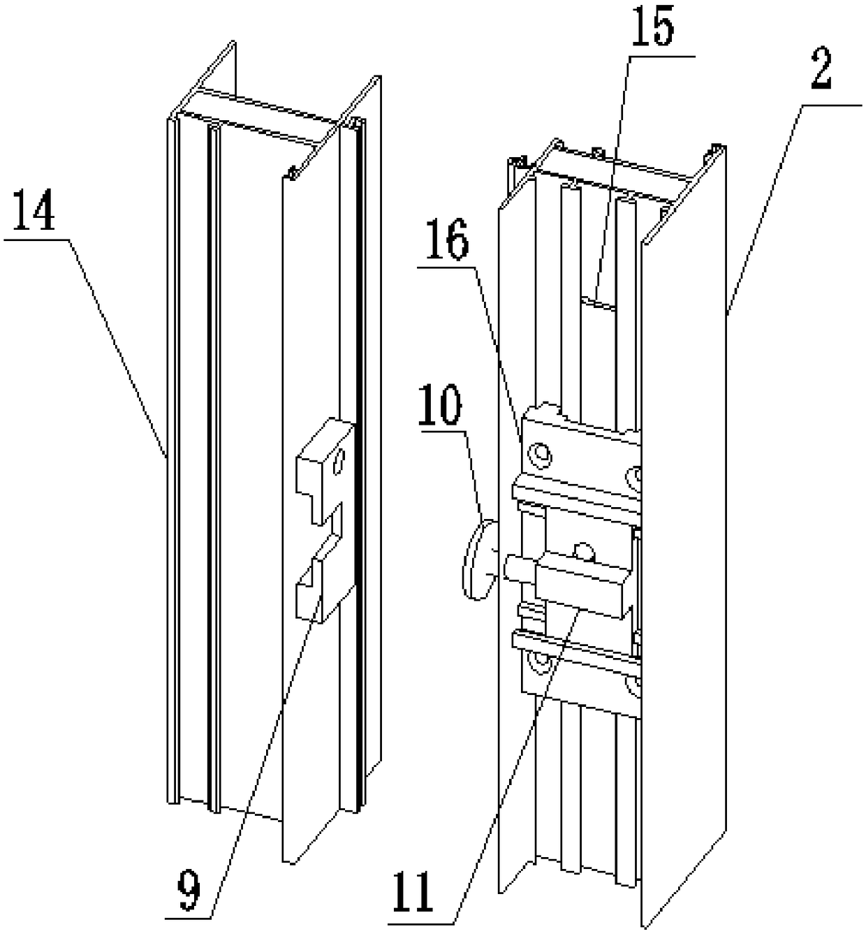
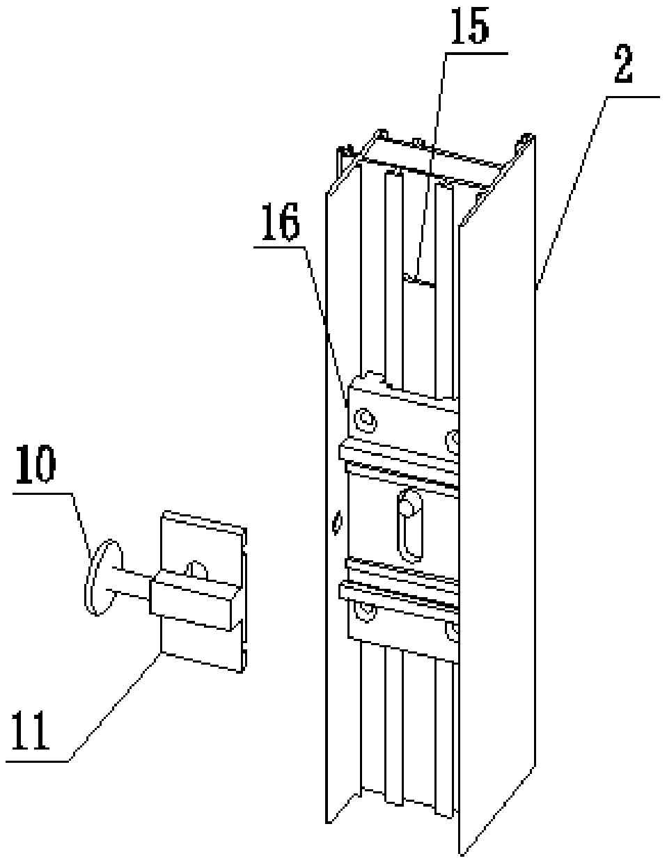
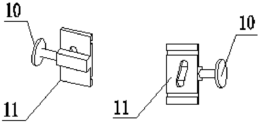
The invention provides a side-pressing sliding door which comprises a door frame, a movable leaf, a fixed leaf and a handle. The fixed leaf and the door frame are fixedly connected, the movable leaf is movably connected with the door frame, the movable leaf can slide left and right relative to the fixed leaf, and the movable leaf is provided with a connecting rod, a connecting block and a base; the base is arranged on the side, close to the fixed leaf when the sliding door is closed, of the movable leaf; the connecting block is movably connected with the base; one end of the connecting rod isfixedly connected with the connecting block, and a mushroom-shaped head is arranged at the other end of the connecting rod; a clamping block is arranged on the edge, away from the door frame, of the fixed leaf and provided with a groove; the handle is arranged on the movable leaf; in the closing process of the sliding door, the mushroom-shaped head enters the groove along with the sliding door, the handle is rotated to enable the mushroom-shaped head to move horizontally to the deep direction and then to be clamped with the clamping block, and the movable leaf is driven to press the fixed leaf; the handle is rotated to the opposite direction, the mushroom-shaped head is reset, and the movable leaf is driven to be away from the fixed leaf. A magnetic rail or a balance wheel is arranged between the upper part of the door frame and the movable leaf to reduce friction, so that pushing and pulling are more convenient and smoother, and high airtightness is always maintained.

Description

Technical field [0001] The present invention relates to the technical field of sliding doors and windows, in particular to a side pressure sliding door. Background technique [0002] In modern buildings, for ventilation, lighting and beauty, sliding doors are often installed between the balcony and the hall, or sliding windows are installed on the windowsill. Most of the sliding doors and windows in the prior art adopt a fixed frame fixed on the wall, and the fan blades are movably connected in the fixed frame through the cooperation of the pulley and the guide rail. However, the fan blades generally have a heavier weight, which makes the friction force generated during the push-pull process larger, and the push-pull force that needs to be applied is larger, which is laborious. In addition, there is a large gap between the fan blades and the fixed frame during installation, resulting in poor sealing performance of doors and windows, vibrations caused by wind blowing, and rainwat...

Claims


Application Information

Patent Timeline
Patent Type & Authority Applications(China)
IPC IPC(8): E06B3/46E06B7/22E05D13/00E05C9/08E05C9/18
CPCE05C9/08E05C9/1825E05D13/00E06B3/4636E06B7/22
Inventor 白雪谢城辉曾顺强邱胜东孟凡东陈俊绮
Owner 广东贝克洛幕墙门窗系统有限公司
Why Eureka
Eureka Blog
Learn More