Shock absorption platform with lifting function and grouter

A function and platform technology, applied in the field of shock absorption platform and grouting machine, can solve the problems of not being able to meet the working environment of bridge slopes, not being able to support platform buffering and protection, and the effect of shock absorption is not ideal, so as to save grouting time and have a novel structure , easy to adjust the effect

Active Publication Date: 2019-03-01
阿克陶县疆源工程建筑有限公司
View PDF6 Cites 14 Cited by
  • Summary
  • Abstract
  • Description
  • Claims
  • Application Information

AI Technical Summary

Problems solved by technology

However, in most cases, the terrain where the grouting machine is required to work is uneven
At present, in engineering practice, in order for the grouting machine to work normally, it is necessary to level the terrain first, which not only takes time, but also affects construction efficiency
At present, the grouting machines on the market will generate great vibration during use, but the existing grouting machine shock absorption measures are not perfect, and the effect of shock absorption is not ideal enough, which cannot meet the satisfaction of users
[0003] Although the above-mentioned invention can adjust the height of the support platform, it has the disadvantages that it cannot meet the working environment of the bridge slope and has poor adaptability, and the grouting machine will vibrate during use, and cannot buffer and protect the support platform. For this reason, we need Develop a shock-absorbing platform with lifting function to solve the above problems

Method used


Image

  • Shock absorption platform with lifting function and grouter
  • Shock absorption platform with lifting function and grouter
  • Shock absorption platform with lifting function and grouter

Examples


Embodiment Construction

[0026] The embodiments of the present invention will be described in detail below with reference to the accompanying drawings, but the present invention can be implemented in various ways defined and covered by the claims.

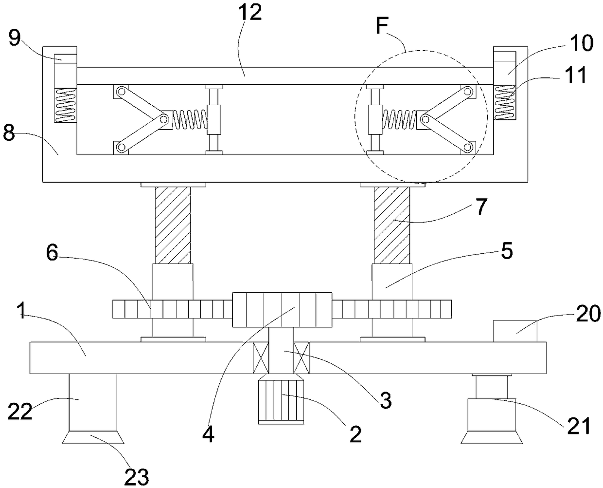
[0027] see figure 1 and figure 2 , the present invention provides a shock absorbing platform with a lifting function, including a base 1, a drive motor 2 is installed in the middle of the bottom of the base 1, a rotating shaft 3 is provided at the output end of the driving motor 2, and the rotating shaft 3 runs through the middle of the base 1 and is connected to the first gear 4 , and the rotation shaft 3 is connected to the base 1, the top of the base 1 is symmetrically provided with a threaded sleeve 5 on both sides, the bottom of the threaded sleeve 5 is connected to the base 1 in rotation, and the middle of the threaded sleeve 5 is provided with a second gear 6 , the second gear 6 is symmetrically arranged on the left and right sides of the first ge...


PUM


Abstract

The invention provides a shock absorption platform with a lifting function and a grouter. The grouter comprises the shock absorption platform with the lifting function. The platform comprises a base,the base is provided with a driving motor, and a rotating shaft is arranged at the output end of the driving motor. The rotating shaft penetrates through the middle part of the base and is connected with a first gear, and the rotating shaft is rotationally connected with the base. Threaded sleeves are symmetrically arranged on the two sides of the top of the base, and the bottoms of the threaded sleeves are rotationally connected with the base. Second gears are arranged on the middle parts of the threaded sleeves in a sleeving manner and are symmetrically arranged on the left side and the right side of the first gear. According to the shock absorption platform with the lifting function and the grouter, the height of the base can be adjusted through a driving cylinder, and the adaptabilityis strong; by the matching of the threaded sleeves and a screw rod, the purpose of adjusting the height of a working platform is achieved, and the grouting efficiency is greatly improved; and meanwhile, under the action of a first shock absorption spring and a second shock absorption spring, the shock absorption effect is achieved, and the shock damage to equipment is reduced.

Description

technical field [0001] The invention relates to the technical field of grouting machines, in particular to a shock-absorbing platform with a lifting function and a grouting machine. Background technique [0002] When the grouting machine is working, it needs to fix the bottom surface on the flat ground. However, in most cases, the terrain where the grouting machine is required to work is uneven. At present, in engineering practice, in order to allow the grouting machine to perform normal operations, it is necessary to level the terrain first, which not only takes time, but also affects construction efficiency. At present, the grouting machines on the market will generate great vibration during use, but the existing grouting machine shock absorption measures are not perfect enough, and the effect of shock absorption is not ideal enough, which cannot meet the satisfaction of users. [0003] Although the above-mentioned invention can adjust the height of the support platform,...

Claims


Application Information

Patent Timeline
Patent Type & Authority Applications(China)
IPC IPC(8): F16M11/04F16M11/24F16F15/04
CPCF16F15/04F16M11/046F16M11/24
Inventor 不公告发明人
Owner 阿克陶县疆源工程建筑有限公司
Why Eureka
Try Eureka