Rotary tiller

A technology for a rotary cultivator and a body is applied in the field of rotary cultivators, and can solve the problems of difficulty in taking into account the matching relationship of transmissions, the inability of rotary cultivators to achieve in-situ rotation reversal, and the complex structure of transmissions.

Pending Publication Date: 2019-03-05
ZOOMLION HEAVY MACHINERY ZHEJIANG CO LTD
View PDF0 Cites 2 Cited by
  • Summary
  • Abstract
  • Description
  • Claims
  • Application Information

AI Technical Summary

Problems solved by technology

However, this kind of transmission is not only complex in structure and high in cost, but also has different transmission efficiencies under different transmission ratios and working conditions. Considering the complexity of the operating conditions of the rotary tiller, it is difficult to take into account the transmission ratio and transmission of the transmission during the design process. The matching relationship between efficiency and operating conditions, especially in plowing operations, requires frequent steering changes, but today's rotary tillers cannot achieve 360° rotation and reversing in situ

Method used


Image

  • Rotary tiller
  • Rotary tiller
  • Rotary tiller

Examples


Embodiment Construction

[0026] The present invention will be further described below in conjunction with the accompanying drawings of the description.

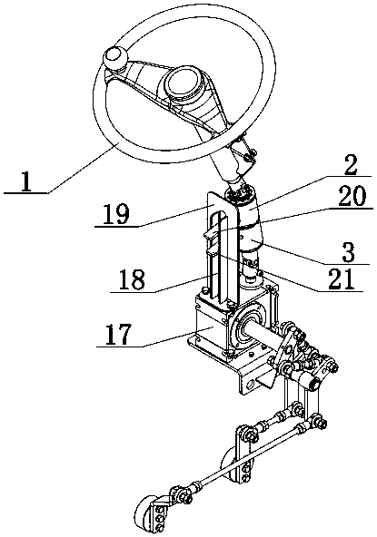
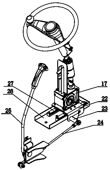
[0027] As shown in the figure, the rotary cultivator includes a body in which a variable speed and reversing transmission mechanism, a 360-degree rotating crawler drive mechanism, and a reduction box for implements are arranged in the body. An engine 62, a pump body assembly 61, and a pump body are also arranged in the body. The assembly 61 includes a first variable pump 29, a second variable pump 30, and a third variable pump 61a. The third variable pump 61a is connected to the implement motor 47 for control. The first variable pump 29 and the second variable pump 30 are respectively connected to the left and right crawler Drive motor control connection.

[0028]The shifting and reversing transmission mechanism includes a reversing transmission mechanism and a shifting lock handle transmission mechanism; the reversing transmission mechanism includes...


PUM


Abstract

A rotary tiller belongs to the technical field of rotary tillers. According to the rotary tiller, the interior of a machine body is provided with a speed-changing direction-changing transmission mechanism, a 360-degree rotating crawler drive mechanism, and a machine speed-reducing box in a cooperative mode. The interior of the machine body is also provided with an engine and a pump body assembly in a cooperative mode, wherein the pump body assembly includes a first variable pump, a second variable pump, and a third variable pump, the third variable pump is in control connection with a machinemotor, and the first variable pump and the second variable pump are connected to left and right crawler-driving motors, respectively. The rotary tiller has a two-stage speed regulation function and ahigh transmission efficiency, and can realize 360-degree rotary reversal in situ; a speed-changing latch handle transmission mechanism has three gear positions, that is, a forward gear position, a neutral gear position and a reverse gear position, and through position control of an entire direction-changing transmission assembly, control on the interiors of the variable pumps is realized, and thespeed of the rotary tiller can be changed; and with the direction-changing transmission mechanism, position change of a crawler-controlled variable pump connection seat can be realized through a smallrotation amount, and thus differential-speed direction change can be realized.

Description

technical field [0001] The invention belongs to the technical field of rotary tillers, in particular to a rotary tiller. Background technique [0002] Rotary tillers are usually used to realize heavy-duty operations such as plowing. The existing rotary tiller transmission shift mechanism and shifting operation are relatively complicated. Existing rotary tillers usually use hydraulic mechanical stepless transmissions, which can transmit more Large load power is an ideal stepless transmission structure for tractors. However, this kind of transmission is not only complex in structure and high in cost, but also has different transmission efficiencies under different transmission ratios and working conditions. Considering the complexity of the operating conditions of the rotary tiller, it is difficult to take into account the transmission ratio and transmission of the transmission during the design process. The matching relationship between efficiency and operating conditions, e...

Claims


Application Information

Patent Timeline
Patent Type & Authority Applications(China)
IPC IPC(8): A01B33/08A01B69/00A01B71/02
CPCA01B33/082A01B69/00A01B71/02
Inventor 肖科玲陈培敏连挺朱儒峰郭鹿浦月东何卫淼冯基平何维勇陈强
Owner ZOOMLION HEAVY MACHINERY ZHEJIANG CO LTD
Why Eureka
Try Eureka