Composite structural slab
A composite structure and panel technology, which is applied to synthetic resin layered products, furniture parts, household appliances, etc., can solve the problems of complex processing, enhanced strength, and high cost, and achieve simplified manufacturing process, enhanced overall load-carrying capacity, and simple structure Effect
- Summary
- Abstract
- Description
- Claims
- Application Information
AI Technical Summary
Problems solved by technology
Method used
Image


Examples
Embodiment Construction
[0039] Descriptions related to directions in any embodiment herein, such as "up / down", "left / right", "top / bottom", etc., are based on the direction of the drawings themselves for the convenience of description, and will not limitations on the invention.
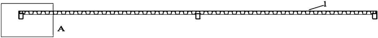
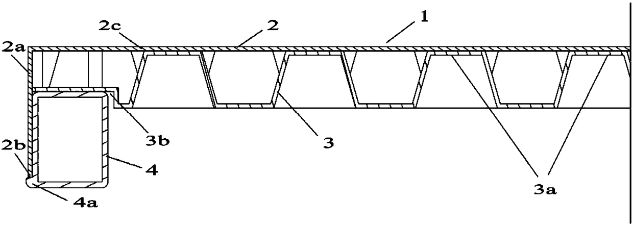
[0040] in such as figure 1 and figure 2 In the shown first embodiment according to the invention, the composite structural panel 1 is mainly composed of three parts: the panel 2 facing outwards in normal use, and the panel 2 fixedly connected to the panel by adhesive or other feasible means. The bottom plate 3 , and the reinforcement 4 provided at the peripheral portions of the panel 2 and the bottom plate 3 .
[0041] The panel 2 has a main body portion 2c substantially on the same plane and a peripheral portion 2a formed by bending the main body portion 2c downward to surround the main body portion, and the panel 2 has an upper surface facing outwards in normal use and The lower surface facing inwards in normal use. A ...
PUM
 Abstract
Description
Claims
Application Information