Wheel expansion device

A technology for expansion devices and wheels, which is applied to rims, vehicle parts, transportation and packaging, etc., can solve the problems of potential safety hazards, high production costs, and high labor intensity, so as to reduce labor intensity, improve production efficiency, and reduce production costs Effect

Inactive Publication Date: 2019-03-05
林继奎
View PDF0 Cites 0 Cited by
  • Summary
  • Abstract
  • Description
  • Claims
  • Application Information

AI Technical Summary

Problems solved by technology

[0002] In the expansion process of the rim line in the domestic steel wheel industry, the automation of the production line has not yet been carried out, and the loading and unloading of the workpiece is completely done manually, with simple personnel functions, high labor intensity, high production costs, and potential safety hazards

Method used


Image

  • Wheel expansion device

Examples


Embodiment Construction

[0010] The present invention will be further described below in conjunction with the accompanying drawings and embodiments.

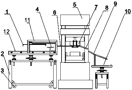
[0011] exist figure 1 Among them, a wheel expansion device, which consists of a lower fixed base 2, an expansion punch 5 and a supporting plate 10, is characterized in that: a transmission belt 12, an upper fixed frame 11 and a lifting device 4 are installed on the lower fixed base 2, The lifting device 4 is symmetrically located on both sides of the transmission belt 12, and the push plate 1 is installed on the top of the upper fixed frame 11. The expansion die 7 of the expansion punching machine 5 is fixedly installed with a loading fixture 6 and a blanking guide column 8. The material receiving guide post 9 is fixedly installed on the plate 10 .

[0012] When working, the wheels are first placed on the conveyor belt 12 on the lower fixed base 2, and the transmission belt 12 drives the wheels to run forward. When running to the lifting device 4, the ...


PUM


Abstract

The invention relates to a wheel expansion device which comprises a lower fixed base, an expansion punching machine and a supporting plate. A transmission belt, an upper fixed frame and lifting devices are arranged on the lower fixed base, the lifting devices are symmetrically positioned on the two sides of the transmission belt, and a push plate is arranged at the top of the upper fixed frame. Aloading clamp and an unloading guide pillar are fixedly arranged on an expansion mould of the expansion punching machine, and a receiving guide pillar is fixedly arranged on the supporting plate.

Description

technical field [0001] The invention relates to a wheel expansion device. Background technique [0002] In the expansion process of the rim line in the domestic steel wheel industry, the automation of the production line has not yet been carried out. The loading and unloading of workpieces is completely done manually, with simple personnel functions, high labor intensity, high production costs, and potential safety hazards. Contents of the invention [0003] The object of the present invention is to solve the deficiencies of the prior art, and to invent an automatic device for expanding the wheel rim. [0004] The technical solution adopted by the present invention to solve the technical problem is: a wheel expansion device, which consists of a lower fixed base, an expansion punch and a supporting plate, and is characterized in that a transmission belt and an upper fixed frame are installed on the lower fixed base And the lifting device, the lifting device is symmetricall...

Claims


Application Information

Patent Timeline
Patent Type & Authority Applications(China)
IPC IPC(8): B21D53/30
CPCB21D53/30
Inventor 林继奎
Owner 林继奎
Why Eureka
Try Eureka