High-energy beam scanning path planning method for manufacturing of addition materials

A scanning path and additive manufacturing technology, applied in the field of high-energy beam scanning path planning, can solve problems that affect the effective use of high-energy beam devices that affect forming efficiency, easy deformation of parts, and difficult inner layer stress, so as to avoid thermal stress accumulation and reduce Deformation, performance-enhancing effects

Inactive Publication Date: 2019-03-05
HUNAN UNIV
View PDF7 Cites 9 Cited by
  • Summary
  • Abstract
  • Description
  • Claims
  • Application Information

AI Technical Summary

Problems solved by technology

Contour offset scanning will make it difficult to release the stress of the inner layer outward, and the workpiece will be easily deformed; the forming effect of the round-trip parallel scanning is better, but it is easy to produce multiple empty strokes when scanning the section with holes or grooves, which affects the forming efficiency and Effective Use of High Energy Beam Devices

Method used


Image

  • High-energy beam scanning path planning method for manufacturing of addition materials
  • High-energy beam scanning path planning method for manufacturing of addition materials
  • High-energy beam scanning path planning method for manufacturing of addition materials

Examples


Embodiment Construction

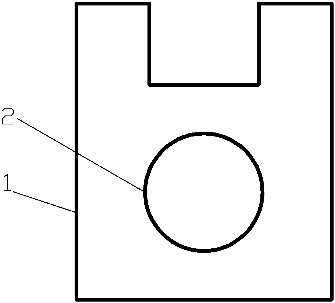
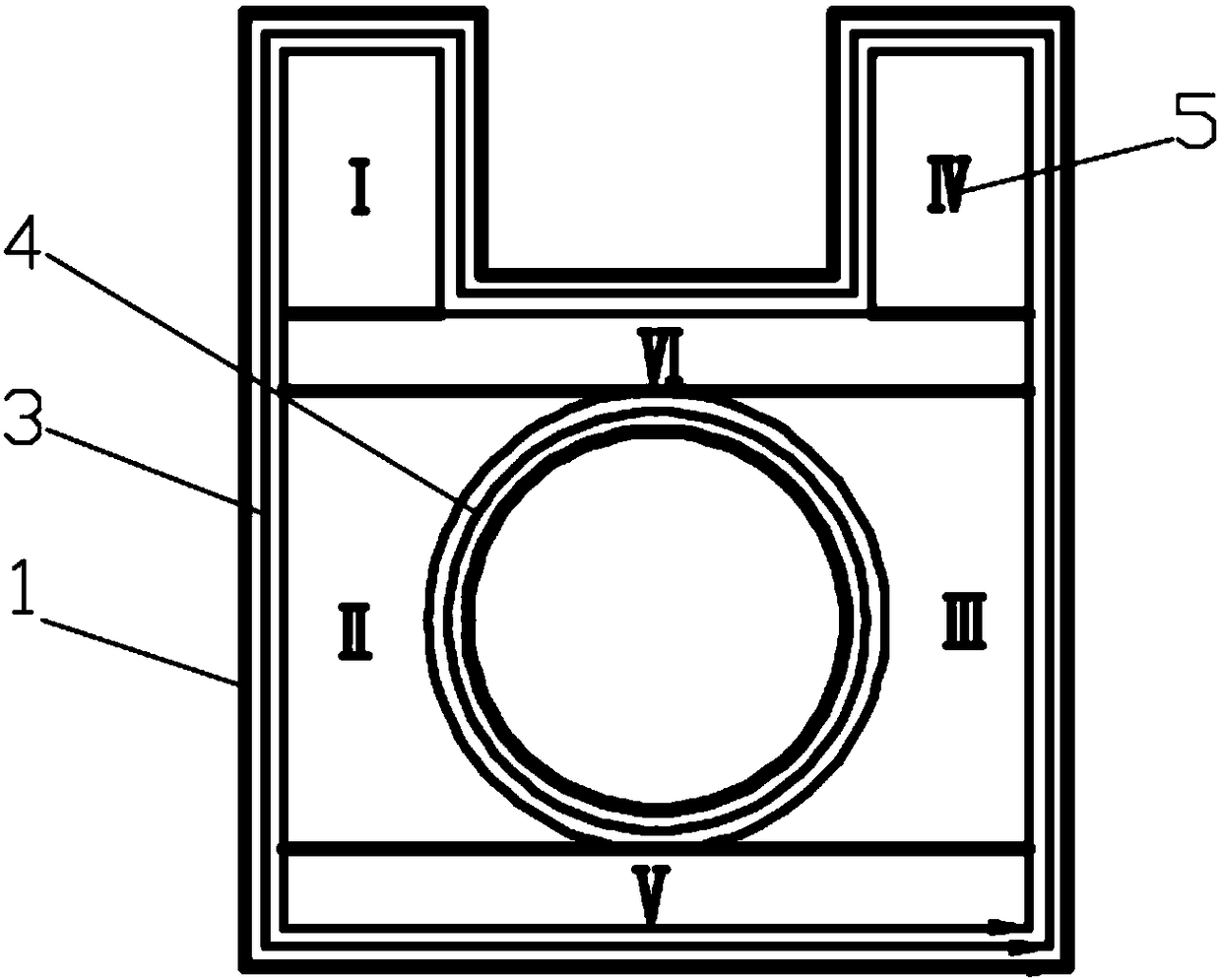
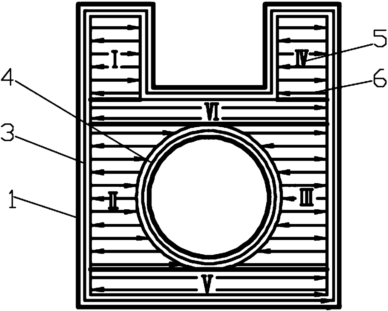
[0012] In conjunction with the accompanying drawings, the implementation process of the present invention is as follows: 1) prepare the additive manufacturing software and hardware system, and determine the process parameters such as high-energy beam power, scanning speed, scanning distance, and slice layer thickness under certain materials and equipment conditions; 2) establish For the 3D digital model of the part to be formed, the 3D digital model file is imported into the additive manufacturing software system, and the computer converts the 3D model into several layers of 2D cross sections according to the slicing rules; 3) sort out the contour data of each layer of 2D cross sections. Dimensional cross-sections such as figure 1 As shown; 4) The outer contour 1 and the inner contour 2 are offset according to a certain scanning distance, and the outer and inner ring offset scanning paths 3 and 4 are generated; 5) The remaining section is partitioned to obtain a partition 5, as...


PUM


Abstract

The invention relates to a high-energy beam scanning method capable of improving shaping quality and efficiency of members and for manufacturing of addition materials. Different scanning paths have important influence on the respects of precision, intensity, buckling deformation and processing efficiency of shaped members. The invention provides the high-energy beam scanning path planning method based on combination of inner outline and outer outline deflexion scanning and interval partition straight line return scanning. The high-energy beam scanning path planning method comprises the following steps of under optimized condition of technological parameters ( including the high-energy beam power, the scanning speed, the overlapping rate and the like ), according to two-dimensional sectioninformation of a digital model to be scanned, firstly performing deflexion scanning along the inner outline and the outer outline of a section for some times, then performing partition on remaining region surrounded by outline deflexion lines, and finally, according to a specific logic sequence, performing return scanning on each partition along parallel straight lines. The high-energy beam scanning path planning method disclosed by the invention has the beneficial effects that thermal stress accumulating is avoided, so that deformation is reduced; idle stroke is reduced, so that efficiency isimproved, and the service life of the high-energy beam device is prolonged; and the dimension precision and surface quality of the shaped members can also be guaranteed, so that the performances of the members are improved.

Description

technical field [0001] The invention relates to a high-energy beam scanning path planning method. Specifically, it relates to a high-energy beam scanning path planning method for additive manufacturing. Background technique [0002] The high-energy beam additive manufacturing process uses the cross-sectional information obtained by layered slicing of the 3D model to control the high-energy beam to melt the material layer by layer and accumulate it into a fully fused (metallurgically bonded) component. In the additive manufacturing process, the process parameters, high-energy beam diameter, and scanning path may have a great impact on the quality of the formed part; at the same time, due to the single-point high-energy loading method, the energy loading and the resulting forming time of each part There is a sequence, the temperature and stress of different positions in the same layer are different due to different scanning sequences, resulting in uneven shrinkage of the work...

Claims


Application Information

Patent Timeline
Patent Type & Authority Applications(China)
IPC IPC(8): B22F3/105
CPCB33Y50/02B22F10/00B22F10/80B22F10/366Y02P10/25
Inventor 刘继常齐利军刘旭东陈阳生
Owner HUNAN UNIV
Why Eureka
Try Eureka