Brake pedal fault diagnosis method and device

A fault diagnosis device and brake pedal technology, applied in the field of vehicles, can solve the problems of high cost, achieve the effects of improving reliability, avoiding fault misjudgment, and reducing fault diagnosis costs

Active Publication Date: 2019-03-05
GREAT WALL MOTOR CO LTD
View PDF5 Cites 12 Cited by
  • Summary
  • Abstract
  • Description
  • Claims
  • Application Information

AI Technical Summary

Problems solved by technology

[0005] In view of this, the present invention aims to propose a brake pedal fault diagnosis method and device to solve the problem that the existing brake pedal fault diagnosis method not only has high cost but also has certain limitations

Method used


Image

  • Brake pedal fault diagnosis method and device
  • Brake pedal fault diagnosis method and device
  • Brake pedal fault diagnosis method and device

Examples


Embodiment 2

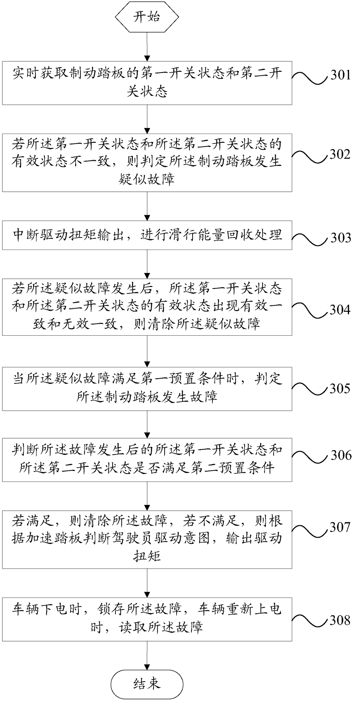
[0070] refer to image 3 , which shows a flow chart of steps of another method for diagnosing brake pedal faults according to an embodiment of the present invention, which may specifically include the following steps:

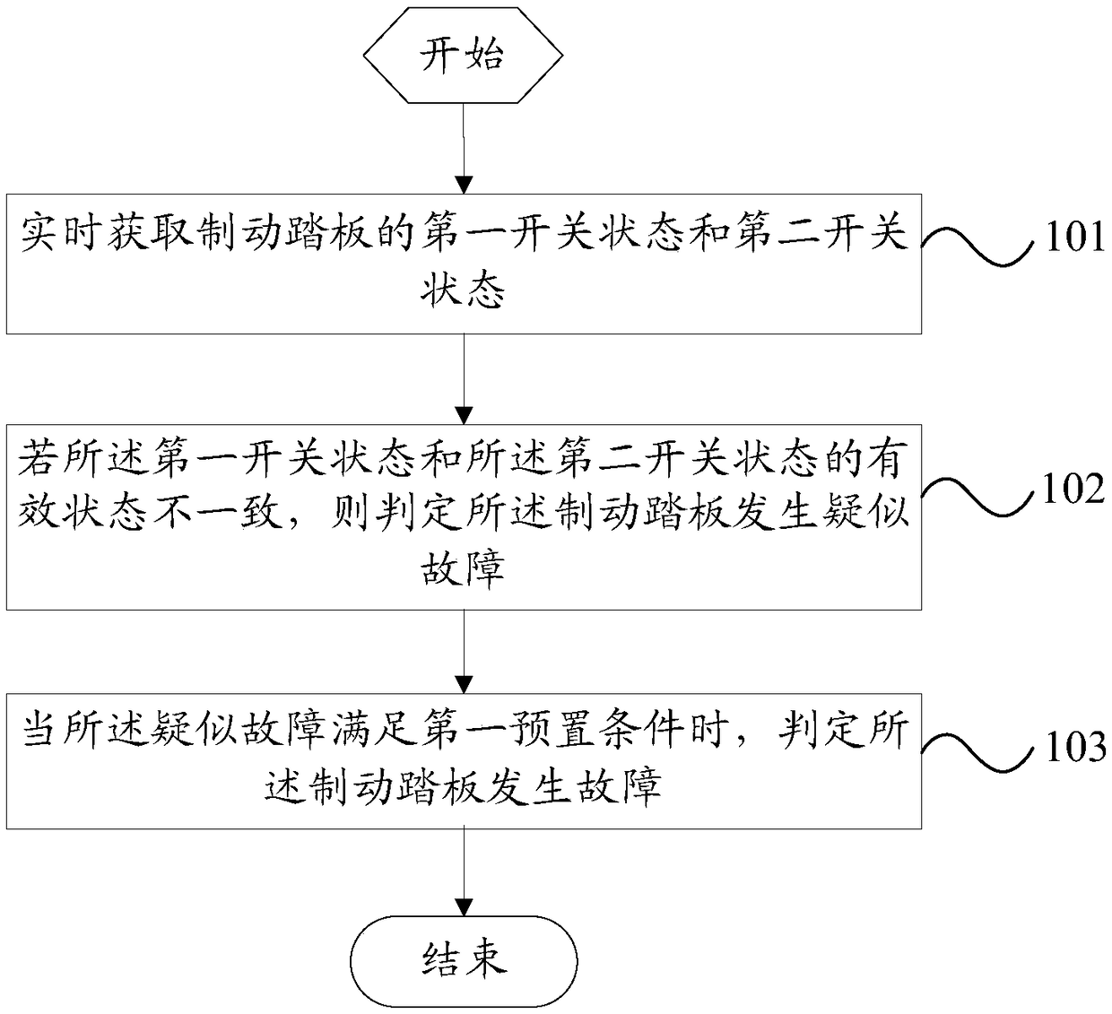
[0071] Step 301: Obtain the first switch state and the second switch state of the brake pedal in real time.

[0072] Step 302: If the effective states of the first switch state and the second switch state are not consistent, determine that a suspected fault has occurred in the brake pedal.

[0073] Step 303: Interrupt the drive torque output, and perform coasting energy recovery processing.

[0074] In the embodiment of the present invention, after it is determined that the brake pedal is suspected to be faulty, the output of the driving torque can be interrupted, and coasting energy recovery processing can be performed, and the vehicle loses power, enters a deceleration coasting state, and stops until it stops.

[0075] In practical applications, when the ve...

Embodiment 3

[0101] refer to Figure 5 , which shows a structural block diagram of a brake pedal fault diagnosis device according to an embodiment of the present invention, which may specifically include:

[0102] The switch state acquisition module 501 is configured to acquire the first switch state and the second switch state of the brake pedal in real time.

[0103] A suspected fault judging module 502, configured to judge that a suspected fault has occurred on the brake pedal if the effective states of the first switch state and the second switch state are inconsistent.

[0104] A fault judging module 503, configured to judge that the brake pedal has a fault when the suspected fault satisfies a first preset condition.

[0105] To sum up, the brake pedal diagnosis device of the embodiment of the present invention has the following advantages:

[0106] First of all, in the embodiment of the present invention, by obtaining the switch state of the brake pedal in real time, the fault of the...

Embodiment 4

[0109] refer to Figure 6 , which shows a structural block diagram of another brake pedal fault diagnosis device according to an embodiment of the present invention, which may specifically include:

[0110] The switch state acquisition module 601 is configured to acquire the first switch state and the second switch state of the brake pedal in real time.

[0111] A suspected fault judging module 602, configured to judge that a suspected fault has occurred on the brake pedal if the effective states of the first switch state and the second switch state are inconsistent.

[0112] The suspected fault processing module 603 is used to interrupt the drive torque output, and perform coasting energy recovery processing.

[0113] The suspected fault clearing module 604 is configured to clear the suspected fault if the effective state of the first switch state and the valid state of the second switch state are consistent with each other when the suspected fault occurs.

[0114] A fault ...


PUM


Abstract

The invention provides a brake pedal fault diagnosis method and device. The brake pedal fault diagnosis method includes the steps that a first on-off state and a second on-off state of a brake pedal are obtained in real time; if the effective states of the first on-off state and the second on-off state are not identical, it is judged that a suspected fault happens to the brake pedal; and when thesuspected fault meets a first preset condition, it is judged that a fault happens to the brake pedal. By the adoption of the brake pedal fault diagnosis method, fault diagnosis of the brake pedal canbe achieved through a simple structure, the fault diagnosis cost of the brake pedal is reduced, fault misjudgment can be avoided to a certain degree, and the fault diagnosis reliability of the brake pedal is improved.

Description

technical field [0001] The invention relates to the technical field of vehicles, in particular to a brake pedal fault diagnosis method and device. Background technique [0002] With the increasing emphasis on energy security and environmental protection, new energy vehicles, such as pure electric vehicles, hybrid vehicles and fuel cell vehicles, have gradually become the development trend of today's automobiles. [0003] In new energy vehicles, the signal of the brake pedal is one of the important input signals for the torque control of the new energy vehicle. The signal of the brake pedal is used as the input judgment condition, so it is necessary to diagnose whether the signal of the brake pedal is normal. [0004] In the existing brake pedal fault diagnosis method, the state signal of the brake pedal is often collected by installing a position sensor on the brake pedal, and the fault diagnosis of the brake pedal is realized by diagnosing the state signal of the brake ped...

Claims


Application Information

Patent Timeline
Patent Type & Authority Applications(China)
IPC IPC(8): B60T17/22
CPCB60T17/22
Inventor 刘宇玲刘伟李贺李雷
Owner GREAT WALL MOTOR CO LTD
Why Eureka
Try Eureka