
washing machine

A washing machine and pulsator technology, applied in the field of washing machines, can solve problems such as the difference in water flow between the upper and lower inner tubs, poor user experience, and entanglement of clothes, and achieve the effects of ensuring cleanliness, reducing material input, and reasonable structure settings

Active Publication Date: 2021-07-30
WUXI LITTLE SWAN ELECTRIC CO LTD
View PDF7 Cites 0 Cited by
  • Summary
  • Abstract
  • Description
  • Claims
  • Application Information

AI Technical Summary

Problems solved by technology

This structural setting makes the pulsator rotate during washing and then drives the water flow near the bottom of the inner tub to rotate to form a strong water flow, but the flow of the water flow at the end far away from the bottom of the inner tub is relatively weak, which leads to a difference in the upper and lower water flow inside the inner tub, resulting in weak washing and clothes Winding and other issues
Especially when washing a lot of clothes or a large-capacity washing machine with a high inner tub is more prone to the above problems, resulting in poor user experience

Method used


Image

  • washing machine
  • washing machine

Examples


Embodiment Construction

[0031] In order to understand the above-mentioned purpose, features and advantages of the present invention more clearly, the present invention will be further described in detail below in conjunction with the accompanying drawings and specific embodiments. It should be noted that, in the case of no conflict, the embodiments of the present application and the features in the embodiments can be combined with each other.

[0032] In the following description, many specific details are set forth in order to fully understand the present invention. However, the present invention can also be implemented in other ways different from those described here. Therefore, the protection scope of the present invention is not limited by the specific details disclosed below. EXAMPLE LIMITATIONS.

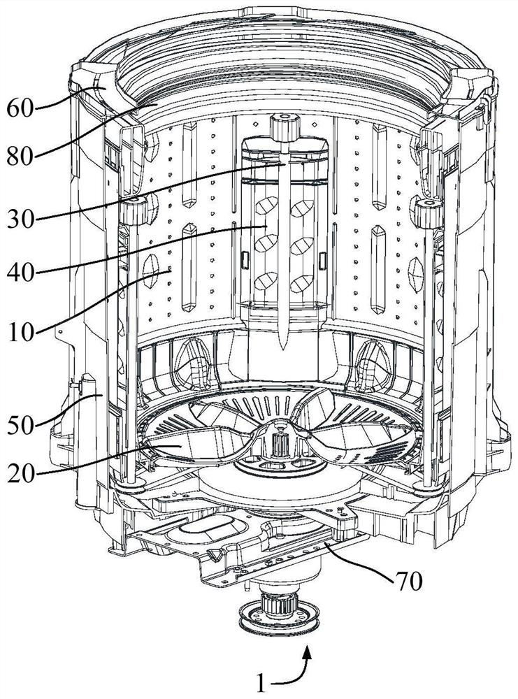
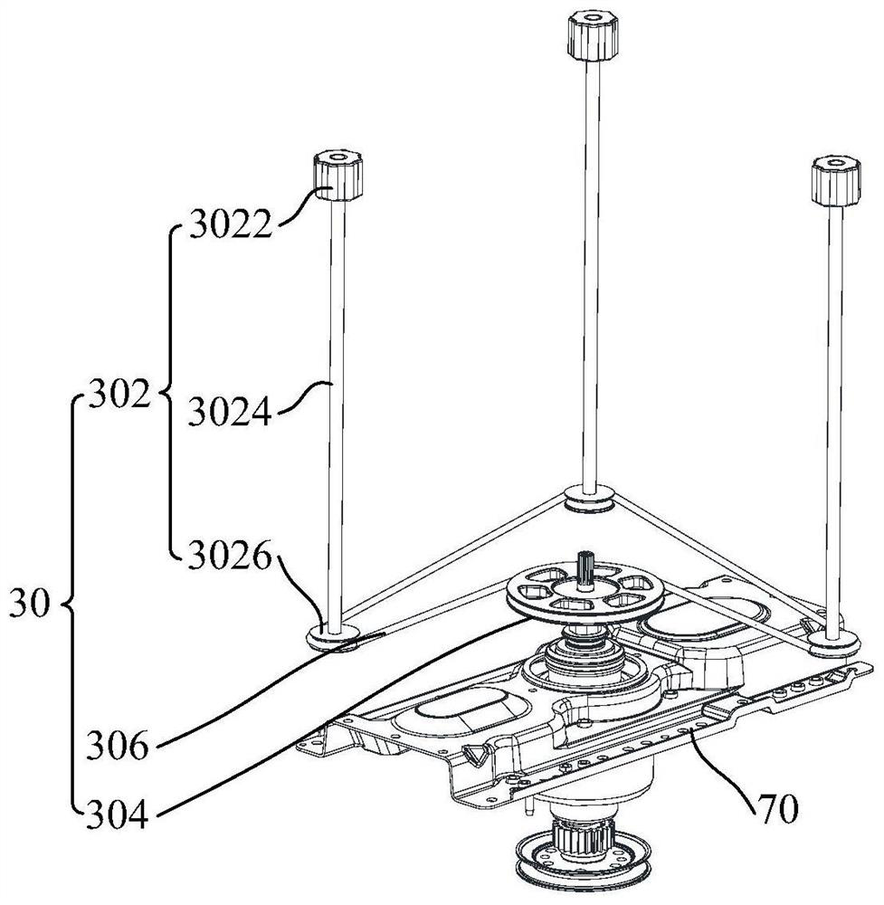
[0033] Refer below figure 1 and figure 2 The washing machine 1 according to some embodiments of the present invention will be described.

[0034] Such as figure 1 and figure 2 As shown, the em...


PUM


Abstract

The invention provides a washing machine, comprising: a dehydration bucket provided with a hollow cavity; a base set on an opening at one end of the cavity; a drive device set in the base; a pulsator set on the base connected to drive The device; the auxiliary pulsator assembly is arranged on the dehydration bucket and is located at one end away from the pulsator, and the auxiliary pulsator assembly is connected to the driving device; wherein, when the washing machine is working, the driving device drives the pulsator and the auxiliary pulsator assembly to rotate. The driving device of the present invention drives the pulsator and the auxiliary pulsator assembly to rotate in forward and reverse directions, so that the water flow in the dehydration bucket can form a strong water flow at the upper and lower ends, thereby improving the friction and washing performance of the laundry items in the washing machine , reducing the probability of clothing entanglement; furthermore, by rationally utilizing the existing structure of the washing machine, the purpose of simultaneously driving the pulsator and the auxiliary pulsator assembly to rotate by the driving device can be achieved without adding an additional power device, thereby reducing production costs.

Description

technical field [0001] The invention relates to the technical field of household appliances, in particular to a washing machine. Background technique [0002] The traditional fully automatic washing machine rotates the washing shaft of the clutch through the motor arranged at the bottom of the outer tub, and then drives the dehydration bucket and the pulsator connected to the washing shaft to rotate, so as to realize the work of washing and dehydration. This structural setting makes the pulsator rotate during washing and then drives the water flow near the bottom of the inner tub to rotate to form a strong water flow, but the flow of the water flow at the end far away from the bottom of the inner tub is relatively weak, which leads to a difference in the upper and lower water flow inside the inner tub, resulting in weak washing and clothes winding and other issues. Especially when washing a lot of clothes or a large-capacity washing machine with a relatively high inner tub ...

Claims


Application Information

Patent Timeline
Patent Type & Authority Patents(China)
IPC IPC(8): D06F17/08D06F17/10
CPCD06F17/08D06F17/10
Inventor 朴锺相尹京强
Owner WUXI LITTLE SWAN ELECTRIC CO LTD
Learn More