Electromagnetic relay

An electromagnetic relay, a pair of technology, applied in the direction of electromagnetic relay, relay, detailed information of electromagnetic relay, etc., can solve problems such as difficult to achieve, high conductivity, etc.

Active Publication Date: 2019-03-05
ORMON CORP
View PDF5 Cites 0 Cited by
  • Summary
  • Abstract
  • Description
  • Claims
  • Application Information

AI Technical Summary

Problems solved by technology

As a result, it may be difficult to achieve high conductivity in the above-mentioned electromagnetic relay

Method used


Image

  • Electromagnetic relay
  • Electromagnetic relay
  • Electromagnetic relay

Examples


Embodiment Construction

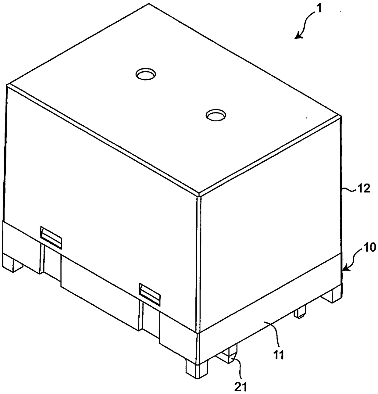
[0052] Hereinafter, an example of the present invention will be described with reference to the drawings. In addition, in the following description, terms indicating specific directions or positions (for example, terms including "upper", "lower", "right", and "left") are used as necessary, but these terms are used for easy understanding The present invention is described with reference to the drawings, and the technical scope of the present invention is not defined by the meanings of these terms. In addition, the following description is only an example in nature, and is not intended to limit this invention, its application, or its use. In addition, the drawings are schematic drawings, and ratios of dimensions and the like do not necessarily match actual ratios.

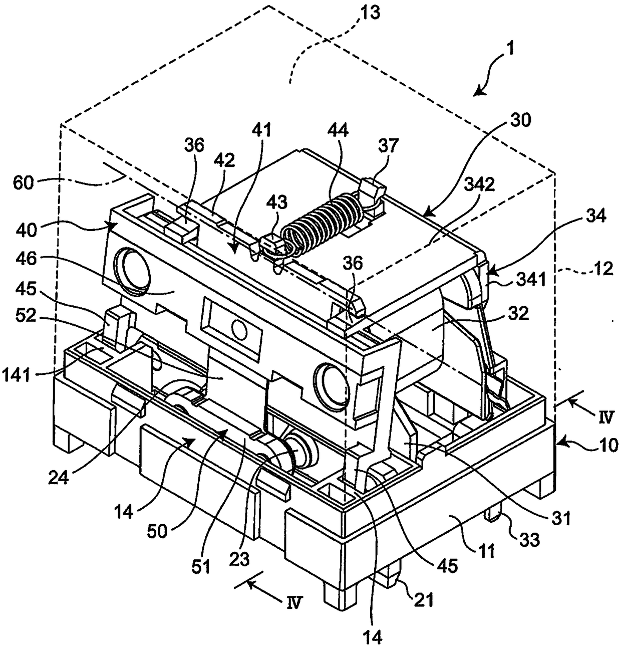
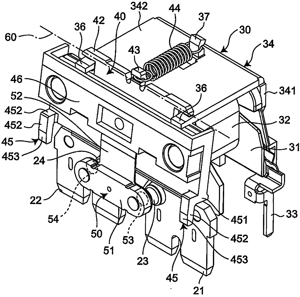
[0053] Such as figure 1 As shown, an electromagnetic relay 1 as an example of the present invention includes a substantially rectangular parallelepiped housing 10 . Such as figure 2 As shown, a pair of fixed ter...


PUM


Abstract

The invention provides an electromagnetic relay having high conductivity. The electromagnetic relay includes a housing, a pair of fixed terminals each having a fixed contact portion, a movable contactpiece having a pair of movable contact portions, and a rotatable movable plate to which the movable contact piece is connected; And an electromagnet unit for rotating the movable plate in the forwardand reverse directions about the rotation axis according to the excitation and the non-excitation. A movable contact piece is connected to the movable plate at an intermediate position in the extending direction of the rotating shaft, and the movable plate is connected to either the movable plate or the position regulating wall at one end of the extending direction of the rotating shaft alternatively, positioning projections are provided so as to face the position restricting wall and to define the return position of the movable plate.

Description

technical field [0001] The invention relates to an electromagnetic relay. Background technique [0002] Patent Document 1 discloses an electromagnetic relay comprising: a cuboid case composed of a base and a cover, a pair of fixed terminals fixed to the bottom surface of the base of the case and each having a fixed contact portion, A spacer of a pair of movable contact parts facing the fixed contact part, and an electromagnet block that rotatably supports the spacer and rotates the spacer according to excitation / de-excitation. [0003] Patent Document 1: Japanese Patent Laid-Open No. 2017-27892 [0004] In the above-mentioned electromagnetic relay, the insulating rib separating the pair of movable contact parts is provided, and the reset position of the spacer (that is, each movable contact part relative to the fixed contact part facing each other) is defined by the rib. position from the farthest barrier). Therefore, the pair of movable contact portions are connected so ...

Claims


Application Information

Patent Timeline
IPC IPC(8): H01H50/58
CPCH01H50/58
Inventor 高桥庆田中弘泰林田靖雄
Owner ORMON CORP
Why Eureka
Try Eureka