Enhanced semiconductor transistor and preparation method thereof
A semiconductor and transistor technology, applied in the field of enhanced semiconductor transistors and their preparation, can solve the problems of p-GaN material growth is difficult to control, p-GaN layer hole concentration is not high, affecting device reliability, etc., to achieve high stability , reduced requirements, and high conduction capability
- Summary
- Abstract
- Description
- Claims
- Application Information
AI Technical Summary
Problems solved by technology
Method used
Image
Examples
Embodiment 1
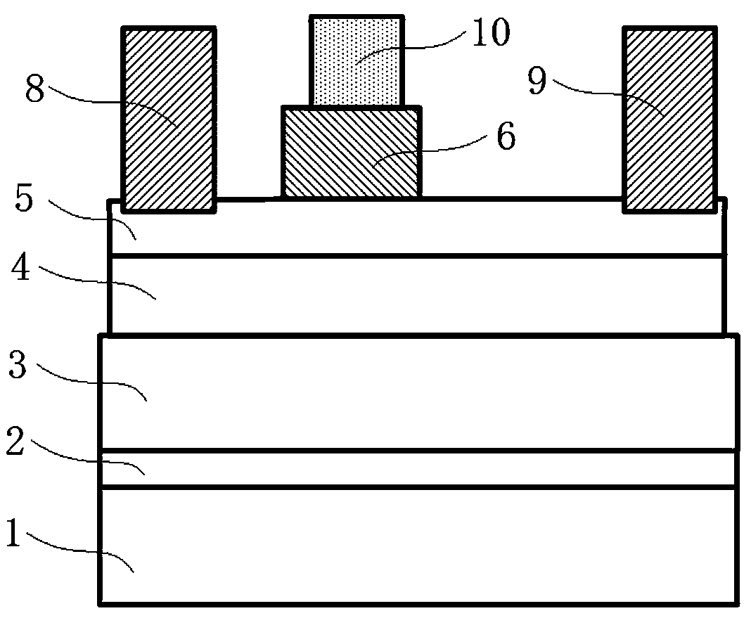
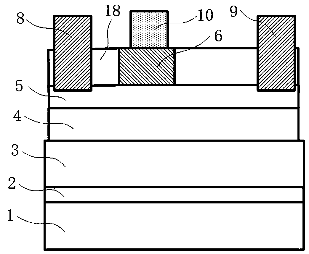
[0056] like Figure 14 Shown is a schematic diagram of the device structure of this embodiment, a semiconductor enhancement transistor, including a substrate 1 , a semiconductor epitaxial layer grown on the substrate 1 , a gate 10 , a source 8 and a drain 9 . Wherein, the epitaxial layer includes, from bottom to top, a nitride nucleation layer 2, a nitride stress buffer layer 3, a nitride channel layer 4, a primary epitaxial nitride barrier layer 5, and a p-type nitride layer 6 and two The sub-epitaxial nitride barrier layer 7 and the p-type nitride layer 6 are only kept on the primary epitaxial nitride barrier layer 5 in the region of the gate 10 to realize the pinch-off of the two-dimensional electron gas channel under the gate 10 . After passing through the mask process, the secondary epitaxial nitride barrier layer 7 is selectively grown on the primary epitaxial nitride barrier layer 5 outside the region of the gate 10 .
[0057] The fabrication method of the above-mentio...
Embodiment 2
[0073] like Figure 15 Shown is a schematic diagram of the device structure of this embodiment, which differs from the structure of Embodiment 1 only in that a layer of AlN space is sandwiched between the nitride channel layer 4 and the primary epitaxial nitride barrier layer 5 in Embodiment 2. The isolation layer 11 has a thickness of 0.3-3 nm. It is used to improve the two-dimensional electron gas characteristics of the channel.
Embodiment 3
[0075] like Figure 16 Shown is a schematic diagram of the device structure of this embodiment, which differs from the structure of Embodiment 1 only in that: Embodiment 1 is middle, and part of the primary epitaxial nitride barrier layer 5 outside the gate 10 region is removed, while Embodiment 3 Part of the primary epitaxial nitride barrier layer 5 outside the region of the middle gate 10 remains intact. Compared with Example 1, Example 3 requires a harsher etching scheme, such as more advanced equipment, or self-terminating etching conditions containing oxygen or fluorine.
PUM
| Property | Measurement | Unit |
|---|---|---|
| thickness | aaaaa | aaaaa |
| thickness | aaaaa | aaaaa |
| thickness | aaaaa | aaaaa |
Abstract
Description
Claims
Application Information
 - R&D
- Intellectual Property
- Life Sciences
- Materials
- Tech Scout
- Unparalleled Data Quality
- Higher Quality Content
- 60% Fewer Hallucinations
Browse by: Latest US Patents, China's latest patents, Technical Efficacy Thesaurus, Application Domain, Technology Topic, Popular Technical Reports.
© 2025 PatSnap. All rights reserved.Legal|Privacy policy|Modern Slavery Act Transparency Statement|Sitemap|About US| Contact US: help@patsnap.com


