Fuel cell press

A technology of fuel cells and compressors, which is applied in the direction of fuel cells, circuits, electrical components, etc., and can solve problems such as difficult assembly of various fuel cells and difficult precise stroke control

Pending Publication Date: 2019-03-05
上海铭寰新能源科技有限公司
View PDF0 Cites 1 Cited by
  • Summary
  • Abstract
  • Description
  • Claims
  • Application Information

AI Technical Summary

Problems solved by technology

[0003] like Image 6 As shown, it is a partial schematic diagram of the existing fuel cell assembly and compaction equipment, including a pressure transmission device, a pressure mold base, an upper mold 701, and a lower mold 702; the fuel cell assembly 800 to be assembled is placed on the upper mold 701, the lower mold Between the molds 702, the pressure transmission device pushes the pressure mold base, so that the upper mold 701 and the lower mold 702 can compress the battery assembly 800; since the pressure tr

Method used


Image

  • Fuel cell press
  • Fuel cell press
  • Fuel cell press

Examples


Embodiment Construction

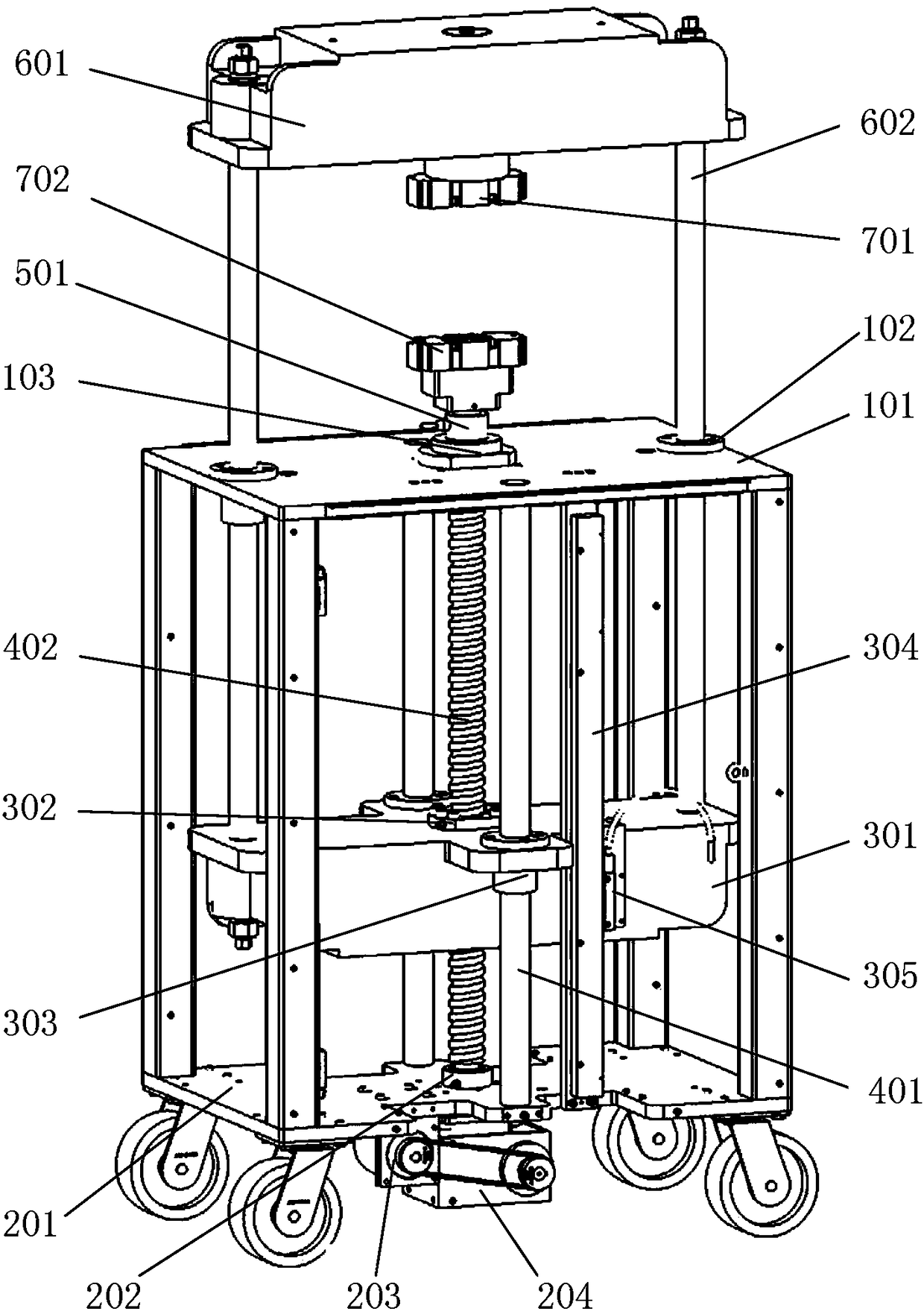
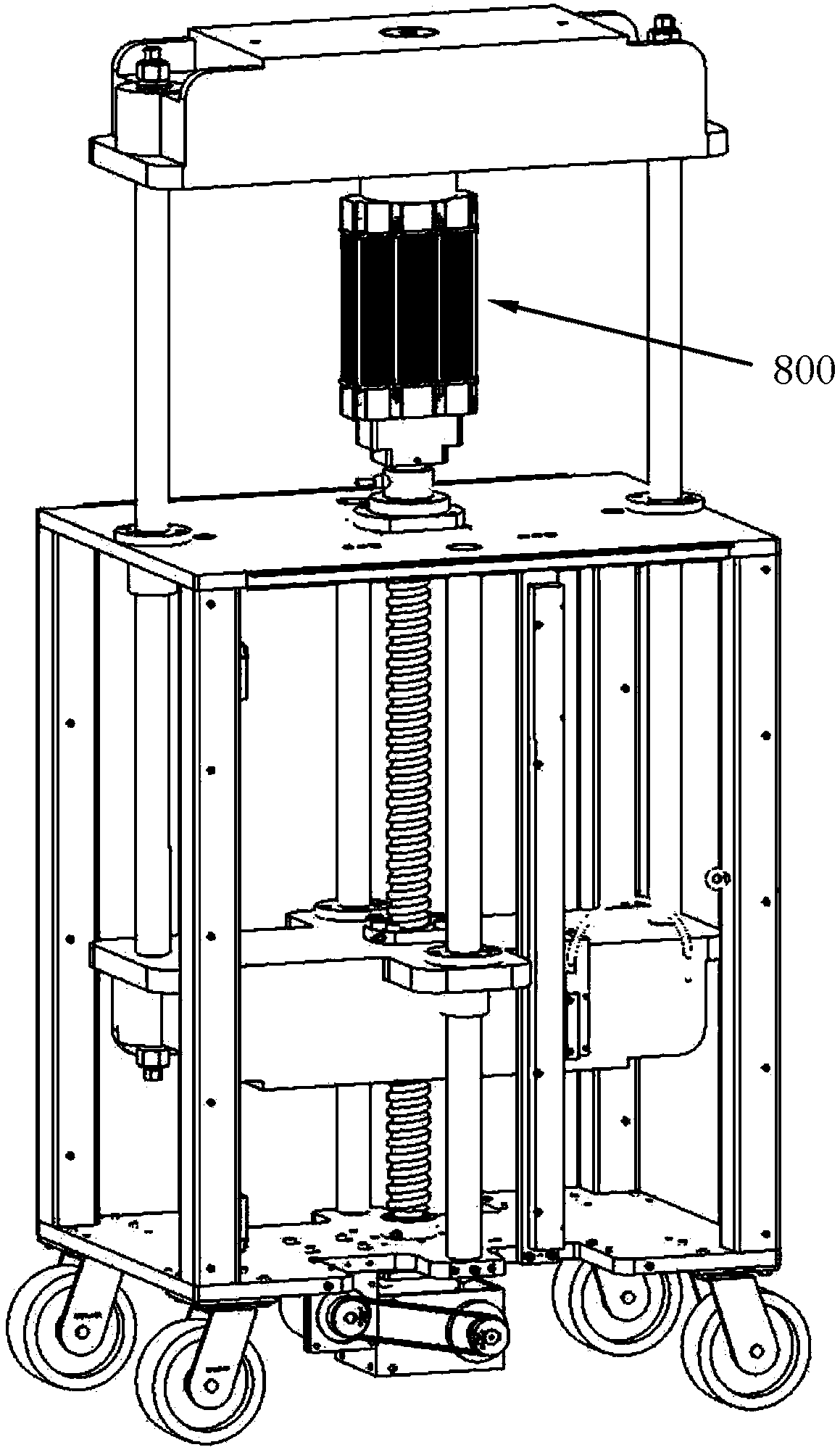
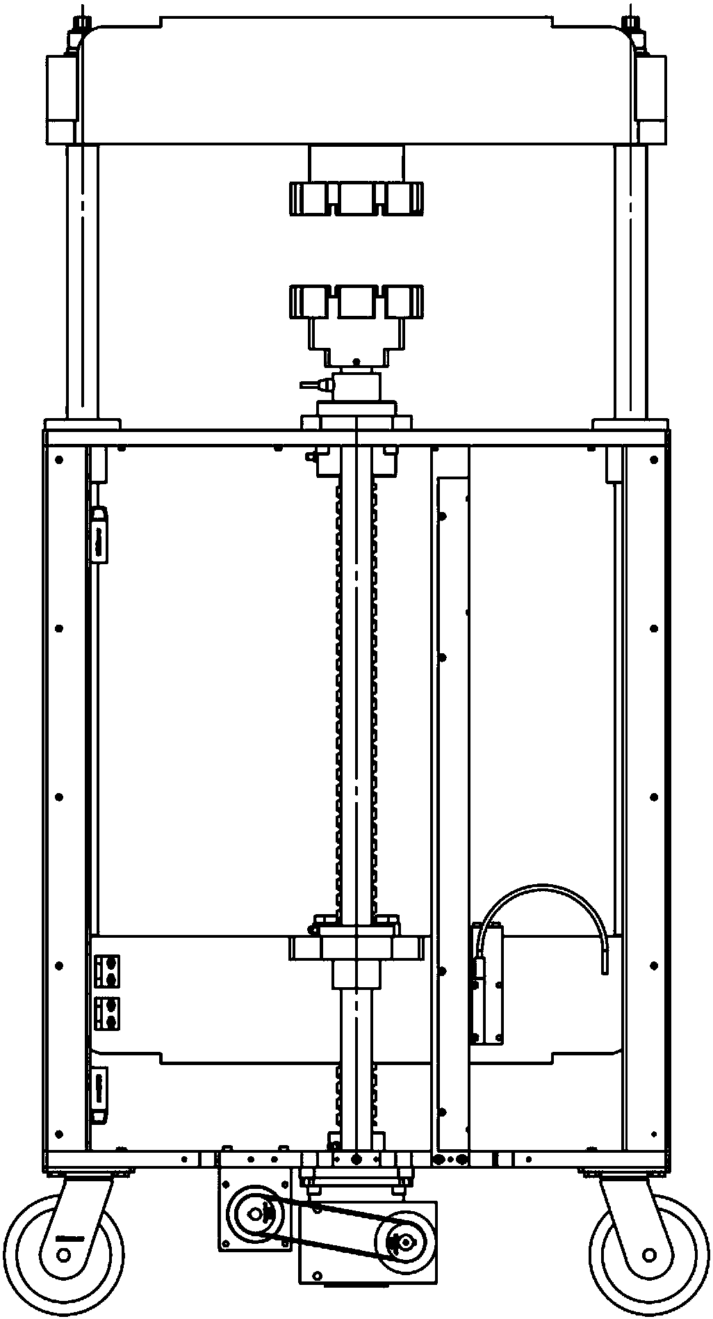
[0028] Figure 1-5 As an embodiment of the present invention, the fuel cell press includes a frame, a power device, a pressure transmission device, an upper mold 701, a lower mold 702, and an electric control system.

[0029] The frame includes a platen 101 and a base plate 201, a guide shaft 401 is arranged between the platen 101 and the base plate 201, a linear grating ruler 304 is arranged between the platen 101 and the base plate 201, and is connected to the base plate 201. The guide shafts 401 are parallel, and a guide fixed bearing 102 and an upper bearing seat 103 are arranged on the platen 101. A deep groove ball bearing and a thrust bearing are arranged in the upper bearing seat 103, and a lower bearing seat 202 is arranged on the bottom plate 201. A deep groove ball bearing and a thrust bearing are arranged in the lower bearing seat 202, the pressure sensor 501 is arranged above the upper bearing seat 103, and the lower mold 702 is arranged above the pressure sensor ...


PUM


Abstract

A fuel cell press provided by the invention belongs to the technical field of fuel cell tooling, and particularly relates to assembly and compacting equipment for fuel cells. The fuel cell press comprises: a frame, a power device, a pressure transmission device, an upper mold, a lower mold, and an electronic control system, wherein the fuel cell press further comprises a linear grating scale, a grating scale head, and a pressure sensor. When the pressure value needs to be controlled, the electronic control system reads the signal of the pressure sensor; when a set pressure value is reached, the numerical control motor is stopped, and then each of the screws around the fuel cell assembly is locked; when the size value needs to be controlled, the electronic control system reads the signal ofthe reading head of the grating scale head, and when the set stroke is reached, the numerical control motor is stopped, and then each of the screws around the fuel cell assembly is locked; and when the numerical control motor is reversed, the upper mold moves upward to take out the assembled fuel cell assembly. After adopting the technical solution, the fuel cell press can be applied to assemblyof various types of fuel cells.

Description

technical field [0001] The invention belongs to the technical field of fuel cell tooling, in particular to assembly and pressing equipment for fuel cells. Background technique [0002] Such as Figure 6 As shown, the fuel cell assembly 800 includes an upper end plate 801, a lower end plate 802, and a single cell 803. The two ends of the screw rod 804 are locked with nuts, and the multiple single cells 803 in the middle are pressed tightly through the upper end plate 801 and the lower end plate 802 to achieve The purpose of airtightness is to prevent fuel leakage; since there are multiple screw rods 804 around the fuel cell assembly 800, it is difficult to ensure that the locking tension of each screw rod 804 is uniform if it is not compressed by a press and assembled directly by tightening the nuts , leading to fuel leakage due to poor sealing; therefore, when assembling the fuel cell, the upper end plate 801 and the lower end plate 802 must be pressed to a certain pressure ...

Claims


Application Information

Patent Timeline
IPC IPC(8): H01M8/248
CPCH01M8/248Y02E60/50
Inventor 郭新新明其敏其他发明人请求不公开姓名
Owner 上海铭寰新能源科技有限公司
Why Eureka
Try Eureka