
Cable box and motor

A technology of cable boxes and motors, which is applied in the direction of electric components, electromechanical devices, electrical components, etc., can solve the problem of inability to adjust the direction of cable leads, and achieve the effect of improving the range of directions and the degree of freedom of adjustment

Active Publication Date: 2020-10-20
SIEMENS AG
View PDF4 Cites 0 Cited by
  • Summary
  • Abstract
  • Description
  • Claims
  • Application Information

AI Technical Summary

Problems solved by technology

In some solutions, the junction box is fixed on the device, and the direction of the cable cannot be adjusted

Method used


Image

  • Cable box and motor
  • Cable box and motor
  • Cable box and motor

Examples


Embodiment Construction

[0032] In order to make the purpose, technical solution and advantages of the present application clearer, the following examples are given to further describe the present application in detail.

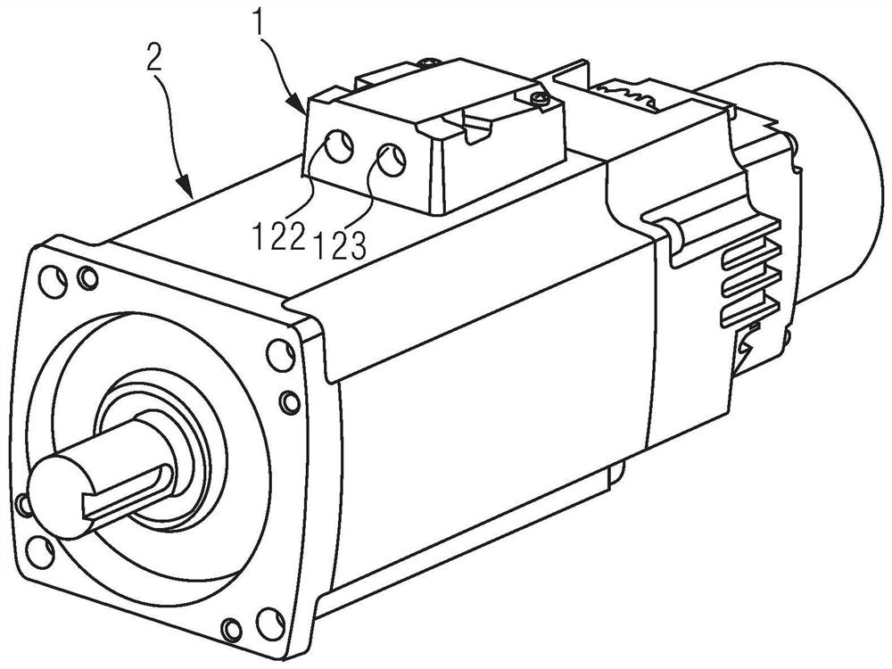
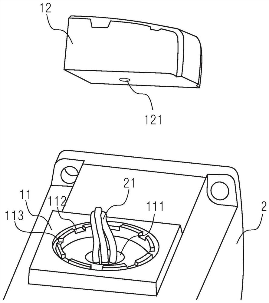
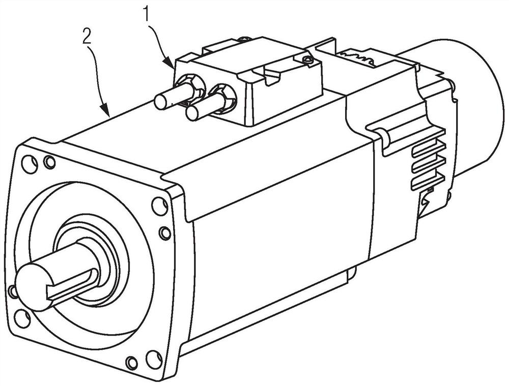
[0033] figure 1 A schematic diagram of an application scenario of a cable box according to some embodiments of the present invention is shown. figure 2 show figure 1 The structure diagram of the cable box in the middle. Such as figure 1 with figure 2 As shown, the cable box 1 is adapted to be mounted on an electric motor 2 . The cable box 1 includes a base 11 and a main body 12 disposed on the base 11 . The base 11 is provided with a first opening 111 through which the cable harness 21 passes. Depending on the cable design of the electric motor 2, the cable bundle 21 may comprise at least one cable. For example, the cable harness 21 includes power supply lines and encoder signal lines, but is not limited thereto. The main body 12 includes a cavity for receiving the cable ha...


PUM


Abstract

The invention discloses a cable box and an electric motor. The cable box which is put forward according to one embodiment of the invention comprises a foundation bed and a main body arranged on the foundation bed, wherein the foundation bed is provided with a first opening through which a cable bundle passes; the main body comprises an empty cavity which contains the cable bundle, a second openingfor the cable bundle to extend into the empty cavity from the first opening, and at least one third opening for at least one part of cable of the cable bundle to extend from the empty cavity; the foundation bed is also annularly provided with a plurality of spacing structures; the bottom of the main body is also provided with a locking structure; and the locking structure can prevent the main body from rotating relative to the foundation bed when the locking structure is cooperated with any one of the plurality of spacing structures.

Description

technical field [0001] The invention relates to the field of motor equipment, in particular to a cable box and a motor. Background technique [0002] In application scenarios related to various mechanical devices such as motors, it is usually necessary to lead out cables, such as power supply lines and signal lines, from the equipment. Here, the power supply line is, for example, a cable for supplying three-phase alternating current. The signal line is, for example, an encoder cable. In order to protect the cables leading out from the equipment (for example, to prevent excessive bending of the cables), the equipment is usually arranged with a junction box. In some solutions, the junction box is fixed on the device, and the direction in which the cables are pulled out cannot be adjusted. Contents of the invention [0003] In view of this, an embodiment of the present invention proposes a cable box to guide cables in a predetermined direction. [0004] A cable box accord...

Claims


Application Information

Patent Timeline
Patent Type & Authority Patents(China)
IPC IPC(8): H02K5/22
CPCH02K5/225
Inventor 孙瑶
Owner SIEMENS AG
Learn More